Ds1874 sfp+ controller with digital ldd interface – Rainbow Electronics DS1874 User Manual
Page 43
DS1874
SFP+ Controller with Digital LDD Interface
______________________________________________________________________________________
43
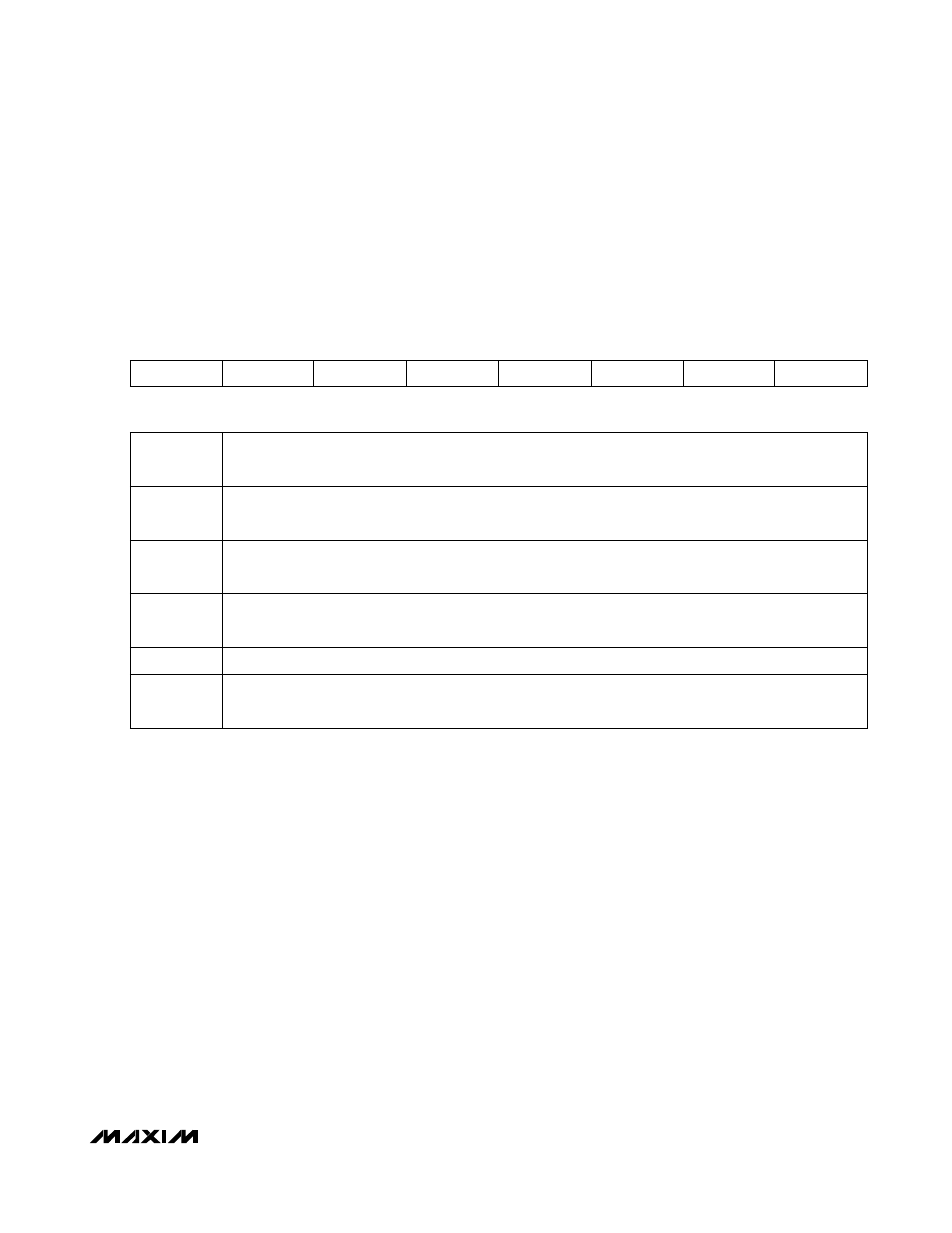
Lower Memory, Register 71h: ALARM
2
POWER-ON
VALUE
00h
READ
ACCESS All
WRITE
ACCESS N/A
MEMORY
TYPE Volatile
71h
MON3 HI
MON3 LO
MON4 HI
MON4 LO
RESERVED
RESERVED
RESERVED
TXFINT
BIT
7
BIT
0
BIT
7
MON3 HI: High-alarm status for MON3 measurement. A TXD event does not clear this alarm.
0 = (Default) Last measurement was equal to or below threshold setting.
1 = Last measurement was above threshold setting.
BIT
6
MON3 LO: Low-alarm status for MON3 measurement. A TXD event does not clear this alarm.
0 = (Default) Last measurement was equal to or above threshold setting.
1 = Last measurement was below threshold setting.
BIT
5
MON4 HI: High-alarm status for MON4 measurement. A TXD event does not clear this alarm.
0 = (Default) Last measurement was equal to or below threshold setting.
1 = Last measurement was above threshold setting.
BIT
4
MON4 LO: Low-alarm status for MON4 measurement. A TXD event does not clear this alarm.
0 = (Default) Last measurement was equal to or above threshold setting.
1 = Last measurement was below threshold setting.
BITS
3:1
RESERVED
BIT
0
TXFINT: TXF Interrupt. This bit is the wire-ORed logic of all alarms and warnings wire-ANDed with their
corresponding enable bits in addition to nonmaskable alarms TXP HI, TXP LO, BIAS MAX, and HBAL. The
enable bits are found in Table 01h, Registers F0h–FFh.