Low-voltage operation, Power-on analog (poa), Delta-sigma outputs (dac1 an – Rainbow Electronics DS1874 User Manual
Page 19: Delta-sigma outputs (dac1 and dac2), Figure 8. low-voltage hysteresis example, Ds1874, Sfp+ controller with digital ldd interface
DS1874
Low-Voltage Operation
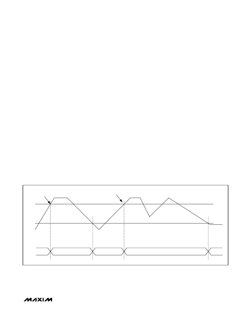
The DS1874 contains two power-on reset (POR) levels.
The lower level is a digital POR (POD) and the higher
level is an analog POR (POA). At startup, before the
supply voltage rises above POA, the outputs are dis-
abled, all SRAM locations are set to their defaults,
shadowed EEPROM (SEE) locations are zero, and all
analog circuitry is disabled. When V
CC
reaches POA,
the SEE is recalled, and the analog circuitry is enabled.
While V
CC
remains above POA, the device is in its nor-
mal operating state, and it responds based on its non-
volatile configuration. If during operation V
CC
falls
below POA, but is still above POD, then the SRAM
retains the SEE settings from the first SEE recall, but the
device analog is shut down and the outputs disabled. If
the supply voltage recovers back above POA, then the
device immediately resumes normal operation. If the
supply voltage falls below POD, then the device SRAM
is placed in its default state and another SEE recall is
required to reload the nonvolatile settings. The EEPROM
recall occurs the next time V
CC
exceeds POA. Figure 8
shows the sequence of events as the voltage varies.
Any time V
CC
is above POD, the I
2
C interface can be
used to determine if V
CC
is below the POA level. This is
accomplished by checking the RDYB bit in the STATUS
(Lower Memory, Register 6Eh) byte. RDYB is set when
V
CC
is below POA; when V
CC
rises above POA, RDYB
is timed (within 500µs) to go to 0, at which point the
part is fully functional.
For all device addresses sourced from EEPROM (Table
02h, Register 8Ch), the default device address is A2h
until V
CC
exceeds POA, allowing the device address to
be recalled from the EEPROM.
Power-On Analog (POA)
POA holds the DS1874 in reset until V
CC
is at a suitable
level (V
CC
> POA) for the device to accurately measure
with its ADC and compare analog signals with its quick-
trip monitors. Because V
CC
cannot be measured by the
ADC when V
CC
is less than POA, POA also asserts the
VCC LO alarm, which is cleared by a V
CC
ADC conver-
sion greater than the customer-programmable V
CC
alarm low ADC limit. This allows a programmable limit
to ensure that the headroom requirements of the trans-
ceiver are satisfied during a slow power-up. The TXF
output does not latch until there is a conversion above
V
CC
low limit. The POA alarm is nonmaskable. The TXF
output is asserted when V
CC
is below POA. See the
Low-Voltage Operation
section for more information.
Delta-Sigma Outputs (DAC1 and DAC2)
Two delta-sigma outputs are provided, DAC1 and
DAC2. With the addition of an external RC filter, these
outputs provide two 9-bit resolution analog outputs with
the full-scale range set by the input REFIN. Each output
SFP+ Controller with Digital LDD Interface
______________________________________________________________________________________
19
V
POA
V
POD
V
CC
SEE
RECALLED VALUE
RECALLED VALUE
PRECHARGED
TO 0
PRECHARGED
TO 0
PRECHARGED TO 0
SEE RECALL
SEE RECALL
Figure 8. Low-Voltage Hysteresis Example