Ds1874 sfp+ controller with digital ldd interface – Rainbow Electronics DS1874 User Manual
Page 47
DS1874
SFP+ Controller with Digital LDD Interface
______________________________________________________________________________________
47
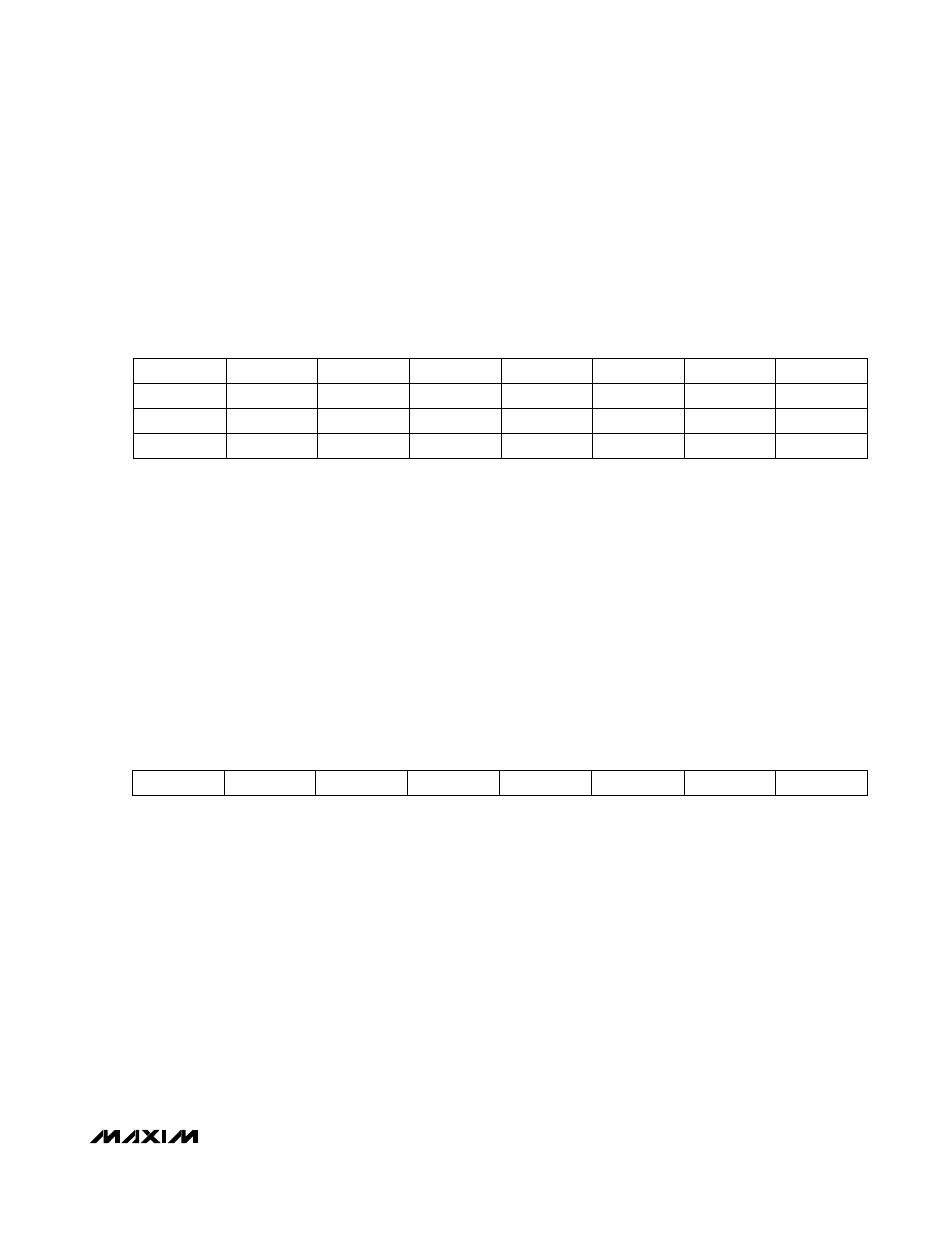
Lower Memory, Register 7Bh–7Eh: Password Entry (PWE)
POWER-ON
VALUE
FFFF
FFFFh
READ
ACCESS N/A
WRITE
ACCESS All
MEMORY
TYPE Volatile
7Bh 2
31
2
30
2
29
2
28
2
27
2
26
2
25
2
24
7Ch 2
23
2
22
2
21
2
20
2
19
2
18
2
17
2
16
7Dh 2
15
2
14
2
13
2
12
2
11
2
10
2
9
2
8
7Eh 2
7
2
6
2
5
2
4
2
3
2
2
2
1
2
0
BIT
7
BIT
0
There are two passwords for the DS1874. Each password is 4 bytes long. The lower level password (PW1) has all the
access of a normal user plus those made available with PW1. The higher level password (PW2) has all the access of
PW1 plus those made available with PW2. The values of the passwords reside in EEPROM inside PW2 memory. At
power-up, all PWE bits are set to 1. All reads at this location are 0.
POWER-ON VALUE
TBLSELPON (Table 02h, Register C7h)
READ
ACCESS All
WRITE
ACCESS All
MEMORY
TYPE Volatile
7Fh 2
7
2
6
2
5
2
4
2
3
2
2
2
1
2
0
BIT
7
BIT
0
The upper memory tables of the DS1874 are accessible by writing the desired table value in this register. The power-on
value of this register is defined by the value written to TBLSELPON (Table 02h, Register C7h).
Lower Memory, Register 7Fh: Table Select (TBL SEL)