Basic operation, Reading the gain meters, User tips – TC Electronic Broadcast 6000 User Manual
Page 114
MDX 5.1
110
System 6000 MKII Algorithms
for instance, different settings for the Center or
Surround channels, where speech intelligibility
or low level ambience tend to get lost. Like when
a feature film is re-purposed for broadcast or
DVD under domestic listening conditions.
If it is required to process more audio channels
than 5.1, Engines can be run in parallel to cater
for 6.1, 7.1, 10.2, 12.2 or even higher number for-
mats. Parallel Engines attain perfect phase con-
servation and resolution, and do not compro-
mise audio in any way.
MDX 5.1 features 48 bit fixed point processing
throughout. Split and reconstruction filters are
phase linear when the algorithm is used in mul-
tiband modes.
Basic operation
The Ref Level parameter on the Main page sets
the unity gain point for all channels (unless gain
offsets are applied), see Fig 2. The Thresholds
on the DXP pages are relative to Ref Level, so
in this particular drawing, Ref Level is set at
-12 dBFS, while most DXP Thresholds are set at
-16 dB. If you invoke the Defeat Threshold, gain
reverts to unity for “below radar” input levels.
Defeat Threshold is relative to DXP Threshold.
In the drawing, the Defeat Threshold is set at
-20 dB
Fig 2. MDX 5.1 Level Diagram for different Steer
and Threshold settings.
Defeat Threshold relates to DXP Threshold which
relates to Ref Level. Limit Threshold only relates
to Digital Full Scale output level.
Note, that the lower the DXP Threshold, or the
higher a Steer setting, the more low level boost
is applied. The low level boost can be different
in different channels, and even in different fre-
quency bands.
Also observe that the Limiter threshold setting is
not relative to Ref Level, but always referenced
to output full scale.
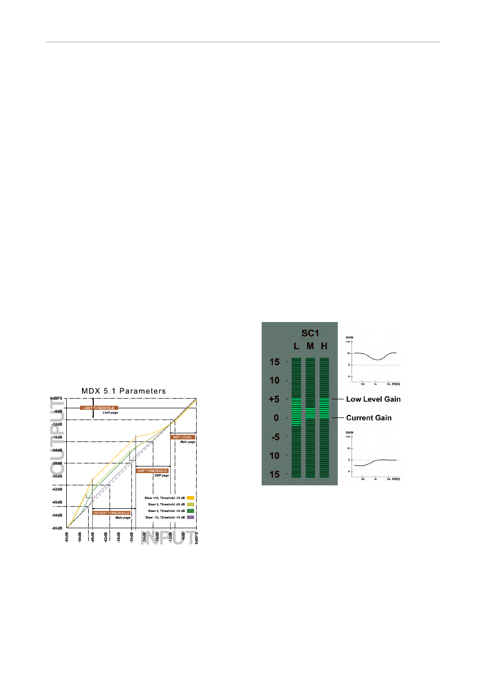
Reading the gain meters
Gain meters in MDX 5.1 indicate absolute gain.
The upper segments of a meter gives an indica-
tion of the boost and frequency response ap-
plied to low level signals, while the lower seg-
ments of a meter gives an indication of the cur-
rent (dynamic) gain and frequency response, see
Fig 3.
In this example, low level signals are subject to
a 5 dB boost in the Low and Hi band. The Low
frequency band is currently attenuated by 2 dB,
while the Mid and Hi bands are at 0 dB gain.
Fig 3. Example of MDX 5.1 Gain Meter.
The meter shows max low level gain and spec-
tral response, plus current gain and spectral
response. In the example, the Low band is cur-
rently attenuated by 2 dB, while Mid and Hi
bands are at unity gain (0 dB).
User tips
At the beginning of a session, it can save time
to set an appropriate difference between the Ref
Level parameter and the Limit Threshold.
Wide dynamic range material for a high resolu-
tion delivery should start with a substantial dif-