Installation guide, Ac power connections, Dc power connections – Veris Industries FSRxxxx SERIES Install User Manual
Page 8: Rc us, Product service
FSRxxxx SERIES
Z205739-0D
PAGE 8
©2013 Veris Industries USA 800.354.8556 or +1.503.598.4564 / [email protected]
05131
Alta Labs, Enercept, Enspector, Hawkeye, Trustat, Aerospond, Veris, and the Veris ‘V’ logo are trademarks or registered trademarks of Veris Industries, L.L.C. in the USA and/or other countries.
TM
INSTALLATION GUIDE
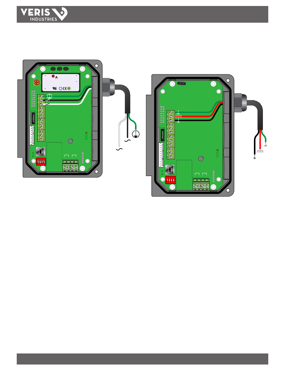
AC Power Connections
Connect 90 to 265 VAC, AC Neutral and Chassis Ground to the terminals referenced in
Figure 1.4. Do not operate without an earth (chassis) ground connection.
D
ownstr
eam
Upstr
eam
+
+
- -
Modbus
TFX Rx
TFX Tx
Signal Gnd.
Control 1
Control 2
Frequency Out
4-20 mA Out
Reset Total
Modbus Gnd
Modbus B
Modbus A
95 - 264 VAC
AC Neutral
W
R
C US
1500mA250V
D
VE
372
R
C US
E167432
$
TUV
PRODUCT SERVICE
RoHS
AC IN : 100-240VAC,50/60Hz
DC OUT :
+15V / 0.3A
PWC-15E
0.15A
R2807
www.astrodyne.com
-Vo
+Vo
ACL
ACN
strodyne
1 2 3 4
O
N
95 - 264 VAC
AC Neutral
Figure 1.4 - AC Power Connections
Note: In electrically noisy applications, ground the meter to the pipe where the transducers are
mounted to provide additional noise suppression. This approach is only effective with conductive
metal pipes. Remove the earth (chassis) ground derived from the line voltage power supply at the
meter and connect a new earth ground between the meter and the pipe being measured.
Note: The terminal blocks accomodate wire gauges up to 14 AWG.
Note: AC powered versions are protected by a field replaceable fuse. This fuse is equivalent to
Littelfuse/Wickmann P.N. 3720500041 or 37405000410.
DC Power Connections
The device can be operated from a 10 to 28 VDC source, as long as the source is
capable of supplying a minimum of 5 Watts of power.
Connect the DC power to 10 to 28 VDC In, Power Gnd., and Chassis Gnd., as in Figure
1.5.
10 - 28 VDC
Power Gnd.
D
ownstr
eam
Upstr
eam
+
+
- -
Modbus
TFX Rx
TFX Tx
1 2 3 4
O
N
Signal Gnd.
Control 1
Control 2
Frequency Out
4-20 mA Out
Reset Total
Modbus Gnd
Modbus B
Modbus A
10 -28 VDC
Power
Ground
10 - 28 VDC
Power Gnd.
Figure 1.5 - DC Power Connections
Note: DC powered versions are protected by an automatically resetting fuse. This fuse does not
require replacement.