Installation guide, Figure 3.4 - typical control connections, Figure 3.5 - single point alarm operation – Veris Industries FSRxxxx SERIES Install User Manual
Page 15
FSRxxxx SERIES
Z205739-0D
PAGE 15
©2013 Veris Industries USA 800.354.8556 or +1.503.598.4564 / [email protected]
05131
Alta Labs, Enercept, Enspector, Hawkeye, Trustat, Aerospond, Veris, and the Veris ‘V’ logo are trademarks or registered trademarks of Veris Industries, L.L.C. in the USA and/or other countries.
TM
INSTALLATION GUIDE
Totalizer Output for Energy Meter
Energy units can be ordered with a totalizer pulse output option. This option is
installed in the position where the Ethernet option would normally be; therefore,
the totalizer pulse output option and the Ethernet communications output cannot be
installed simultaneously.
Optional totalizing pulse specifications:
Signal
1 pulse for each increment of the totalizer’s least significant digit
Type
Opto-isolated, open collector transistor
Pulse Width
30 msec, max. pulse rate 16 Hz
Voltage
28 VDC max.
Current
100 mA max. (current sink)
Pull-up Resistor
2.8 kΩ to 10 kΩ
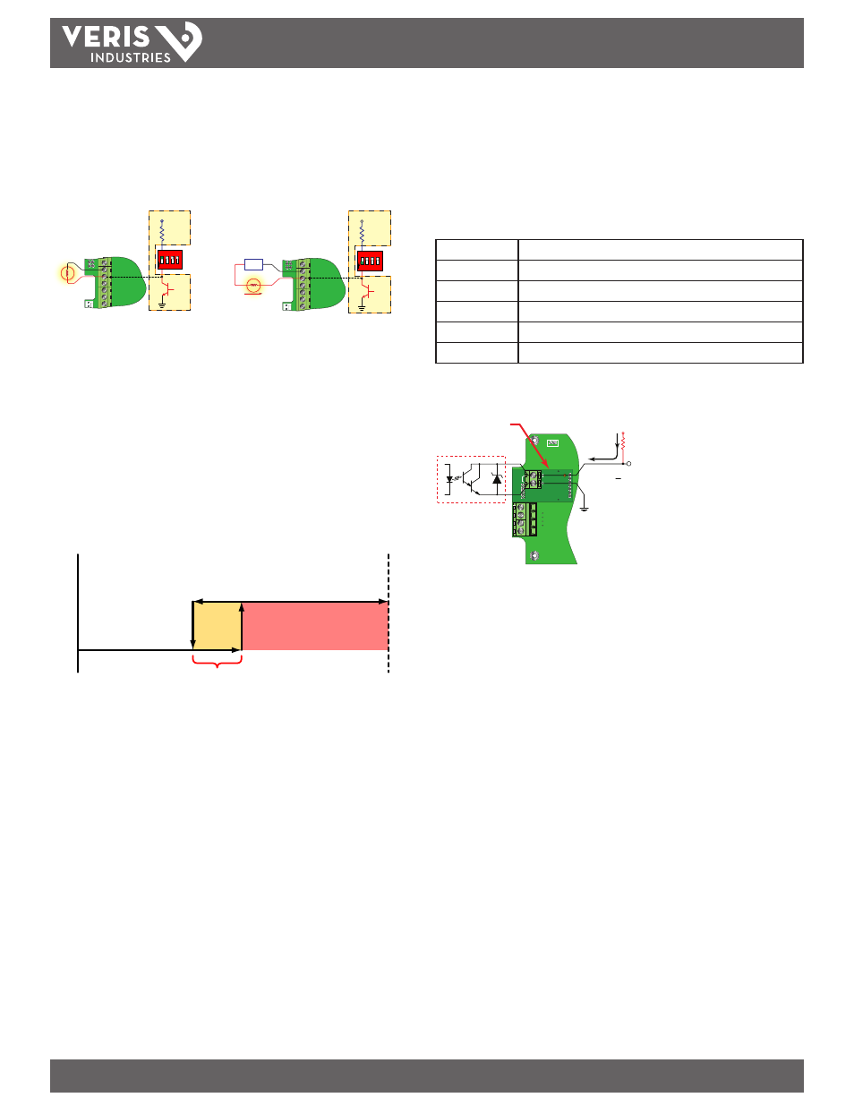
Wiring and configuring this option is similar to the totalizing pulse output for the
flow only version. This option must use an external current limiting resistor.
Totalizing
Pulse Output
Option
Total
Pulse
RxD
TB1
Isolated Output
Total Pulse
Internal
2.8K to 10K
Pull-up
Resistor
V
CC
100 mA
Maximum
Signal Strength Alarm
The SIG STR alarm provides an indication that the signal level reported by the
transducers has fallen to a point where flow measurements may not be possible.
It can also be used to indicated that the pipe has emptied. Like the rate alarm
described previously, the signal strength alarm requires that two points be entered,
establishing an alarm deadband. The ON value must be lower than the OFF value. If a
deadband is not established and the signal strength decreases to approximately the
value of the switch point, the output may “chatter.”
Error Alarm Outputs
When a control output is set to ERROR mode, the output activates when an error
causes the meter to stop measuring reliably. See the Appendix of this manual for a list
of potential error codes.
Set the on/off values for the Rate Alarm and Signal Strength Alarm using either the
keypad or the software utility.
Typical control connections are illustrated in Figure 3.4. Please note that only
the Control 1 output is shown. Control 2 is identical except the pull-up resistor is
governed by SW2.
SW1/SW2
90-265 VAC
AC Neutral
Signal Gnd.
Control 2
Frequency Out
4-20 mA Out
Reset Total
10K
VCC
1 2 3 4
O
N
Control 1
10K
VCC
SW1/SW2
90-265 VAC
AC Neutral
Signal Gnd.
Control 2
Frequency Out
4-20 mA Out
Reset Total
Control 1
1 2 3 4
O
N
10 - 28
VDC
100 mA Maximum
Figure 3.4 - Typical Control Connections
Alarm Output
The flow rate output permits output changeover at two separate flow rates allowing
operation with an adjustable switch deadband. Figure 3.5 illustrates how the setting
of the two set points influences rate alarm operation.
A single-point flow rate alarm places the ON setting slightly higher than the OFF
setting, establishing a switch deadband. If a deadband is not established, switch
chatter (rapid switching) may result if the flow rate is very close to the switch point.
Minimum
Flow
Maximum
Flow
Output ON
Set OFF
Set ON
Deadband
Output OFF
Figure 3.5 - Single Point Alarm Operation
Batch/Totalizer Output
Totalizer mode configures the output to send a 33 mSec pulse each time the display
totalizer increments divided by the TOT MULT. The TOT MULT value must be a whole,
positive, numerical value.
Fir example, If the totalizer exponent (TOTL E) is set to E2 (×100) and the totalizer
multiplier (TOT MULT) is set to 1, then the control output pulses each time the display
totalizer increments or once per 100 measurement units totalized.