Veris Industries HS Install User Manual
Hs sensor replacement
TM
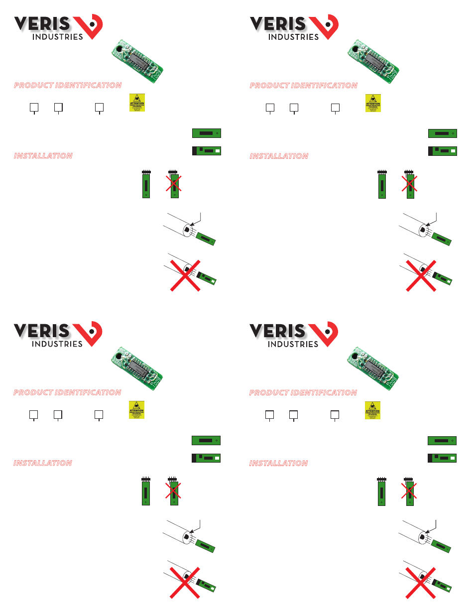
HS SENSOR
REPLACEMENT
Z205266-0B
08113
The microprocessor-profiled
capacitive HS element can be
replaced in the field without
calibration.
PRODUCT IDENTIFICATION
Accuracy
NIST
N = NIST (1% and
2% models only)
X = None (2%, 3%,
and 5% models
only)
1 = 1%*
2 = 2%
3 = 3%
5 = 5%
HS
X
INSTALLATION
For all unit types, ensure that the four HS pin holes are
inserted fully onto the unit pin connectors.
Humidity Outdoor and Duct Units
1. Disconnect power to the unit.
2. Remove probe from junction box by loosening black
swage nut and sliding out.
3. Unscrew filter on tip of probe. Set filter aside.
4. Remove HS element by gently pulling from pin
connector. Do not attempt to remove temperature
sensor adjacent to HS element (if equipped).
5. Place new HS element onto pin connector. Orient as
shown, or unit will not function (filter will not screw
on if HS is inserted incorrectly).
6. Replace filter. Re-insert probe into junction box and
tighten swage nut.
HS sensor elements are sold as open devices.
Observe handling precautions for static sensitive
devices to avoid damage to the circuitry which
would not be covered under the factory warranty.
Temp sensor
(if equipped)
Top
Side
Bottom
Side
Top
Side
Bottom
Side
TM
HS SENSOR
REPLACEMENT
Z205266-0B
08113
The microprocessor-profiled
capacitive HS element can be
replaced in the field without
calibration.
PRODUCT IDENTIFICATION
Accuracy
NIST
N = NIST (1% and
2% models only)
X = None (2%, 3%,
and 5% models
only)
1 = 1%
2 = 2%
3 = 3%
5 = 5%
HS
X
INSTALLATION
For all unit types, ensure that the four HS pin holes are
inserted fully onto the unit pin connectors.
Humidity Outdoor and Duct Units
1. Disconnect power to the unit.
2. Remove probe from junction box by loosening black
swage nut and sliding out.
3. Unscrew filter on tip of probe. Set filter aside.
4. Remove HS element by gently pulling from pin
connector. Do not attempt to remove temperature
sensor adjacent to HS element (if equipped).
5. Place new HS element onto pin connector. Orient as
shown, or unit will not function (filter will not screw
on if HS is inserted incorrectly).
6. Replace filter. Re-insert probe into junction box and
tighten swage nut.
HS sensor elements are sold as open devices.
Observe handling precautions for static sensitive
devices to avoid damage to the circuitry which
would not be covered under the factory warranty.
Temp sensor
(if equipped)
Top
Side
Bottom
Side
Top
Side
Bottom
Side
* 1% HS sensors used in outdoor
applications are limited by the
device to 2% accuracy.
* 1% HS sensors used in outdoor
applications are limited by the
device to 2% accuracy.
* 1% HS sensors used in outdoor
applications are limited by the
device to 2% accuracy.
* 1% HS sensors used in outdoor
applications are limited by the
device to 2% accuracy.