Installation guide – Veris Industries FSRxxxx SERIES Install User Manual
Page 10
FSRxxxx SERIES
Z205739-0D
PAGE 10
©2013 Veris Industries USA 800.354.8556 or +1.503.598.4564 / [email protected]
05131
Alta Labs, Enercept, Enspector, Hawkeye, Trustat, Aerospond, Veris, and the Veris ‘V’ logo are trademarks or registered trademarks of Veris Industries, L.L.C. in the USA and/or other countries.
TM
INSTALLATION GUIDE
Mounting
Mode
Pipe Material
Pipe Size
Liquid
Composition
W-Mount
Plastic (all types)
2-4 in. (50-100 mm)
Low TSS; non-aerated
Carbon Steel
Stainless Steel
Copper
Ductile Iron
Not Recommended
Cast Iron
V-Mount
Plastic (all types)
4-12 in. (100-300 mm)
Carbon Steel
Stainless Steel
Copper
4-30 in. (100-750 mm)
Ductile Iron
2-12 in. (50-300 mm)
Cast Iron
Z-Mount
Plastic (all types)
> 30 in. (>750 mm)
Carbon Steel
>12 in. (>300 mm)
Stainless Steel
Copper
> 30 in. (>750 mm)
Ductile Iron
>12 in. (>300 mm)
Cast Iron
Table 2.2 - Transducer Mounting Modes — FST4, FST5
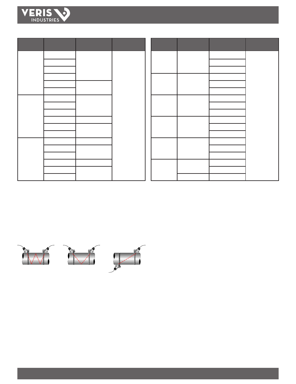
For further details, reference Figure 2.1. The appropriate mounting configuration is
based on pipe and liquid characteristics. Selection of the proper transducer mounting
method is not entirely predictable and many times is an iterative process. Table 2.2
contains recommended mounting configurations for common applications. These
recommended configurations may need to be modified for specific applications
if such things as aeration, suspended solids, out of round piping or poor piping
conditions are present. Use of meter diagnostics in determining the optimum
transducer mounting is covered later in this section.
TOP VIEW
OF PIPE
TOP VIEW
OF PIPE
TOP VIEW
OF PIPE
W-Mount
V-Mount
Z-Mount
Figure 2.1- Transducer Mounting Modes — FST4, FST5
Size
Frequency
Setting
Transducer
Mounting Mode
1/2
2 MHz
FST1
V
FST2
FST3
3/4
2 MHz
FST1
FST2
FST3
1
2 MHz
FST1
FST2
FST3
1 1/4
2 MHz
FST1
FST2
FST3
1 1/2
2 MHz
FST1
FST2
FST3
2
1 MHz
FST1
FST2
2 MHz
FST3
Table 2.3 - Transducer Mounting Modes — FST1, FST2, FST3
Step 3 - Entering Pipe and Liquid Data
The system calculates proper transducer spacing by utilizing piping and liquid
information entered by the user. Enter this information via the keypad or via the
optional software utility.
The best accuracy is achieved when transducer spacing is exactly what the meter
calculates, so use the calculated spacing if signal strength is satisfactory. If the pipe is
not round, the wall thickness is not correct, or the actual liquid being measured has a
different sound speed than the liquid programmed into the transmitter, the spacing
can vary from the calculated value. If that is the case, place the transducers sat the
highest signal level observed by moving the transducers slowly around the mount
area.
Note: Transducer spacing is calculated on “ideal” pipe. Ideal pipe is almost never found so the
transducer spacing distances may need to be altered. An effective way to maximize signal strength
is to configure the display to show signal strength, fix one transducer on the pipe and then starting
at the calculated spacing, move the remaining transducer small distances forward and back to
find the maximum signal strength point.
Important! Enter all of the data on this list, save the data, and reset the
meter before mounting transducers.