Installation guide, Step 4 - transducer mounting, V-mount and w-mount installation – Veris Industries FSRxxxx SERIES Install User Manual
Page 11
FSRxxxx SERIES
Z205739-0D
PAGE 11
©2013 Veris Industries USA 800.354.8556 or +1.503.598.4564 / [email protected]
05131
Alta Labs, Enercept, Enspector, Hawkeye, Trustat, Aerospond, Veris, and the Veris ‘V’ logo are trademarks or registered trademarks of Veris Industries, L.L.C. in the USA and/or other countries.
TM
INSTALLATION GUIDE
The following information is required before programming the instrument:
Transducer mounting configuration
Pipe O.D. (Outer Diameter)
Pipe wall thickness
Pipe material
Pipe sound speed
1
Pipe relative roughness
1
Pipe liner thickness (if present)
Pipe liner material (if present)
Fluid type
Fluid sound speed
1
Fluid viscosity
1
Fluid specific gravity
1
Note: Much of the data relating to material sound speed, viscosity, and specific gravity is
pre-programmed into the flow meter. This data only needs to be modified if it is known that a
particular applications data varies from the reference values. Refer to Part 4 of this manual for
instructions on entering configuration data into the flow meter via the monitor’s keypad. Refer to
Part 5 for data entry via the software.
1
Nominal values for these parameters are included within the operating system. The nominal
values may be used as they appear or may be modified if exact system values are known.
After entering the data listed above, the meter calculates proper transducer spacing
for the particular data set. This distance is in inches if it is configured in English units,
or millimeters if configured in metric units.
Step 4 - Transducer Mounting
Pipe Preparation
Before mounting the transducers onto the pipe surface, clean an area slightly larger
than the flat surface of each transducer to eliminate all rust, scale and moisture.
For pipes with rough surfaces, such as ductile iron pipe, wire brush the surface to a
shiny finish. Paint and other coatings need not be removed unless flaked or bubbled.
Plastic pipes typically do not require surface preparation other than soap and water
cleaning.
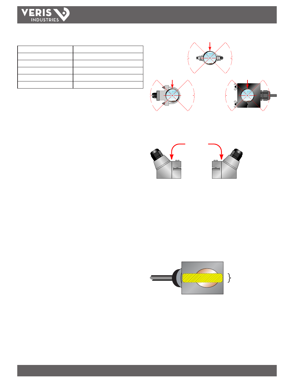
Properly orient the transducers and spaced them on the pipe to provide optimum
reliability and performance. On horizontal pipes, when Z-Mount is required, mount
the transducers 180 radial degrees from one another and at least 45 degrees from
the top-dead-center and bottom-dead-center of the pipe. See Figure 2.2 Also see
Z-Mount Transducer Installation. On vertical pipes the orientation is not critical.
Measure the spacing between the transducers using the two spacing marks on the
sides of the transducers. These marks are approximately 0.75” (19 mm) back from the
nose of the FST4/FST5 transducers. See Figure 2.3.
Mount FST1, FST2, and FST3 transducers with the cable exiting within ±45 degrees
of the side of a horizontal pipe. See Figure 2.2. On vertical pipes the orientation does
not apply.
45°
45°
YES
YES
45°
45°
FLOW METER
MOUNTING ORIENTATION
<2” FST1, FST2, FST3 TRANSDUCERS
45°
45°
YES
YES
45°
45°
FLOW METER MOUNTING
ORIENTATION
FST4, FST5 TRANSDUCERS
TOP OF PIPE
45°
45°
YES
YES
45°
45°
FLOW METER
MOUNTING ORIENTATION
2” FST1, FST2, FST3 TRANSDUCERS
TOP OF PIPE
TOP OF PIPE
Figure 2.2 - Transducer Orientation — Horizontal Pipes
Alignment
Marks
Figure 2.3 - Transducer Alignment Marks
V-Mount and W-Mount Installation
Application of Couplant
For FST4 and FST5 transducers, place a single bead of couplant, approximately ½
inch (12 mm) thick, on the flat face of the transducer. See Figure 2.4. Generally, a
silicone-based grease is used as an acoustic couplant, but any grease-like substance
that is rated not to “flow” at the temperature that the pipe may operate at will be
acceptable. For pipe surface temperature over 130°F (55°C) Sonotemp® (P.N. D002-
2011-010) is recommended.
½”
(12 mm)
Figure 2.4 - Application of Couplant