Veris Industries VST11 (-4) Install User Manual
Notice, Danger, Track mount 10 amp spdt relay
Z204230-0C
PAGE 1
©2012 Veris Industries USA 800.354.8556 or +1.503.598.4564 / [email protected]
07122
Alta Labs, Enercept, Enspector, Hawkeye, Trustat, Veris, and the Veris ‘V’ logo are trademarks or registered trademarks of Veris Industries, L.L.C. in the USA and/or other countries.
TM
Relays
INsTallaTION GUIDe
Track Mount 10 Amp SPDT Relay
Installer’s Specifications
Operating Temperature
0° to 60°C (32° to 140°F)
Operating Humidity
10-90% RH, non-condensing
Relay Status
LED ON=energized
Auxiliary Supply for HOA
24VAC/DC (supplied from a Class 2 or LVLE source)*
Expected Relay Life
Electrical (@ rated current) 100,000 cycles;
Mechanical
(unpowered) 10,000,000 cycles
Terminal Block Torque
0.5 to 3.5 in-lb (0.68 to 4.75 N-m)
Insulation Class
600VAC RMS (coil to contact); 120VAC RMS (terminal to surface)
Agency Approvals
UL508 open device listing; Installation Category III, pollution degree 2
*Class 2 source: A source that provides a Class 2 power supply as defined by the NEC, NFPA-70.
LVLE: Low voltage limited energy, not capable of providing more than 30VAC/42.4VDC, 8A or
100VA
VST10 (-4), VST11 (-4) VST10 (-4), VST11 (-4)
NOTICE
• This product is not intended for life or safety applications.
• Do not install this product in hazardous or classified locations.
• The installer is responsible for conformance to all applicable codes.
• Mount this product inside a suitable fire and electrical enclosure.
HAZARD OF ELECTRIC SHOCK, EXPLOSION, OR ARC FLASH
• Follow safe electrical work practices.
See NFPA 70E in the USA, or applicable local codes.
• This equipment must only be installed and serviced by qualified electrical personnel.
• Read, understand and follow the instructions before installing this product.
• Turn off all power supplying equipment before working on or inside the equipment.
• Use a properly rated voltage sensing device to confirm power is off.
DO NOT DEPEND ON THIS PRODUCT FOR VOLTAGE INDICATION
Failure to follow these instructions will result in death or serious injury.
DANGER
SNAP
SNAP
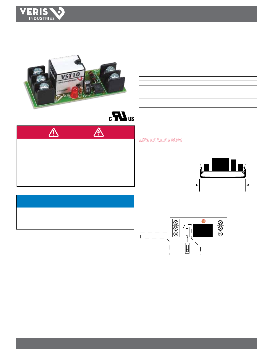
VSTxx: 2.75” (70 mm)
VSTxx-4: 4” (102 mm)
installation
Disconnect and lock out all power sources before beginning the
installation.
1. Snap the VST into a mounted
track of the appropriate size.
2. Connect the coil terminals as indicated below. The status LED is closest to the load
terminals. Use a single 24 VAC/DC Class 2 or low-voltage limited energy (LVLE),
power source. Fusing is mandatory if the control voltage supply can provide > 4 A.
COIL COMMON
COIL Input 24VAC/DC
AUX Input 24VAC/DC
OFF
AUTO
HAND
NC Contact
COMMON Contact
NO Contact
VST11s
Only
3. Connect the contact terminals to the load(s), as required.
4. If using a VST11 or VST11-4, set the HOA switch to the correct position for your
application, Hand, Auto, or Off. If using the Hand position, connect the 24 VAC/DC
coil power to the AUX terminal to power the switch.
5. Secure the enclosure and reconnect power.