Installation guide, Rc us, Product service – Veris Industries FSRxxxx SERIES Install User Manual
Page 17: Minc o, Figure 3.13 - connecting rtds, Minco, Figure 3.11 - surface mount rtd installation
FSRxxxx SERIES
Z205739-0D
PAGE 17
©2013 Veris Industries USA 800.354.8556 or +1.503.598.4564 / [email protected]
05131
Alta Labs, Enercept, Enspector, Hawkeye, Trustat, Aerospond, Veris, and the Veris ‘V’ logo are trademarks or registered trademarks of Veris Industries, L.L.C. in the USA and/or other countries.
TM
INSTALLATION GUIDE
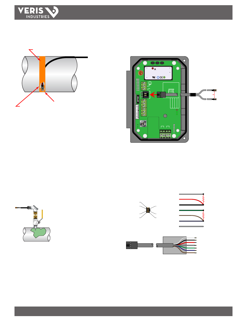
Wiring to Meter
After the RTDs have been mounted to the pipe, route the cable back to the meter
through the middle hole in the enclosure. Connect to the meter inserting the RTD
connector into the mating connector on the circuit board.
95 - 264 VAC
AC Neutral
Signal Gnd.
4-20 mA Out
Reset Total
Modbus Gnd
Modbus B
Modbus A
D
ownstr
eam
Upstr
eam
+
+
- -
RTD 1 RTD 2
TEMP
. SE
T
0 t
o 50°C
0 t
o 100°C
-40 t
o 200°C
Modbus
TFX Rx
TFX Tx
Exc.
Sig.
Gnd.
Shield
Exc.
Sig.
Gnd.
Shield
W
R
C US
1500mA250V
D
VE
372
R
C US
E167432
$
TUV
PRODUCT SERVICE
RoHS
AC IN : 100-240VAC,50/60Hz
DC OUT :
+15V / 0.3A
PWC-15E
0.15A
R2807
www.astrodyne.com
-Vo
+Vo
ACL
ACN
strodyne
RETURN LINE
RTD #2
MINC
O
SUPPLY LINE
RTD #1
MINC
O
RTD’s
Figure 3.13 - Connecting RTDs
Replacement RTDs
Complete RTD kits, including the energy meters plug-in connector and calibration
values for the replacements, are available from the manufacturer.
It is also possible to use other manufacturer’s RTDs. The RTDs must be 1000 Ω
platinum RTDs suitable for a three-wire connection. A connection adapter is available
to facilitate connection to the meter. See Figure 3.14.
PIN #1
PIN #3
PIN #5
PIN #2
PIN #4
PIN #6
PIN #8
RTD2
RTD1
WHITE
RED
BLACK
GREEN
BROWN
BLUE
DRAIN
WHITE
BLACK
RED
GREEN
BLUE
BROWN
DRAIN
PIN#3
PIN#6
PIN#1
PIN#8
PIN#4
PIN#2
PIN#5
Figure 3.14 - RTD Adapter Connections
Note: It will be necessary to calibrate third party RTDs to the meter for proper operation. See the
Appendix of this manual for the calibration procedure.
Route the RTD cables back to the flow meter and secure the cable so that it will not be
pulled on or abraded inadvertently. Replace the insulation on the pipe, ensuring that
the RTDs are not exposed to air currents.
MINCO
Clean RTD Mounting
Area to Bare Metal Surface
Heat Sink
Compound
Heat Tape
Figure 3.11 - Surface Mount RTD Installation
Installation of Insertion RTDs
Insertion RTDs are typically installed through ¼ inch (6 mm) compression fittings
and isolation ball valves. Insert the RTD sufficiently into the flow stream such that a
minimum of ¼ inch (6 mm) of the probe tip extends into the pipe diameter. Only use
insertion (wetted) RTDs on pipes that are not insulated.
Mount RTDs within ±45 degrees of the side of a horizontal pipe. On vertical pipes the
orientation is not critical. Route the RTD cables back to the flow meter and secure the
cable so that it will not be pulled on or abraded inadvertently.
If the cables are not long enough to reach the meter, route the cables to an electrical
junction box and add additional cable from that point. Use three-wire shielded cable,
such as Belden® 9939 or equal, for this purpose.
Note: Adding cable adds to the resistance the meter reads and may have an effect on absolute
accuracy. If cable is added, ensure that the same length is added to both RTDs to minimize errors
due to changes in cable resistance.
Figure 3.12 - Insertion Style RTD Installation