Installation guide, Heat flow [btu meters only, Frequency output [fsrxxx1x only – Veris Industries FSRxxxx SERIES Install User Manual
Page 16: Rs-485, Figure 3.10 - rtd schematic
FSRxxxx SERIES
Z205739-0D
PAGE 16
©2013 Veris Industries USA 800.354.8556 or +1.503.598.4564 / [email protected]
05131
Alta Labs, Enercept, Enspector, Hawkeye, Trustat, Aerospond, Veris, and the Veris ‘V’ logo are trademarks or registered trademarks of Veris Industries, L.L.C. in the USA and/or other countries.
TM
INSTALLATION GUIDE
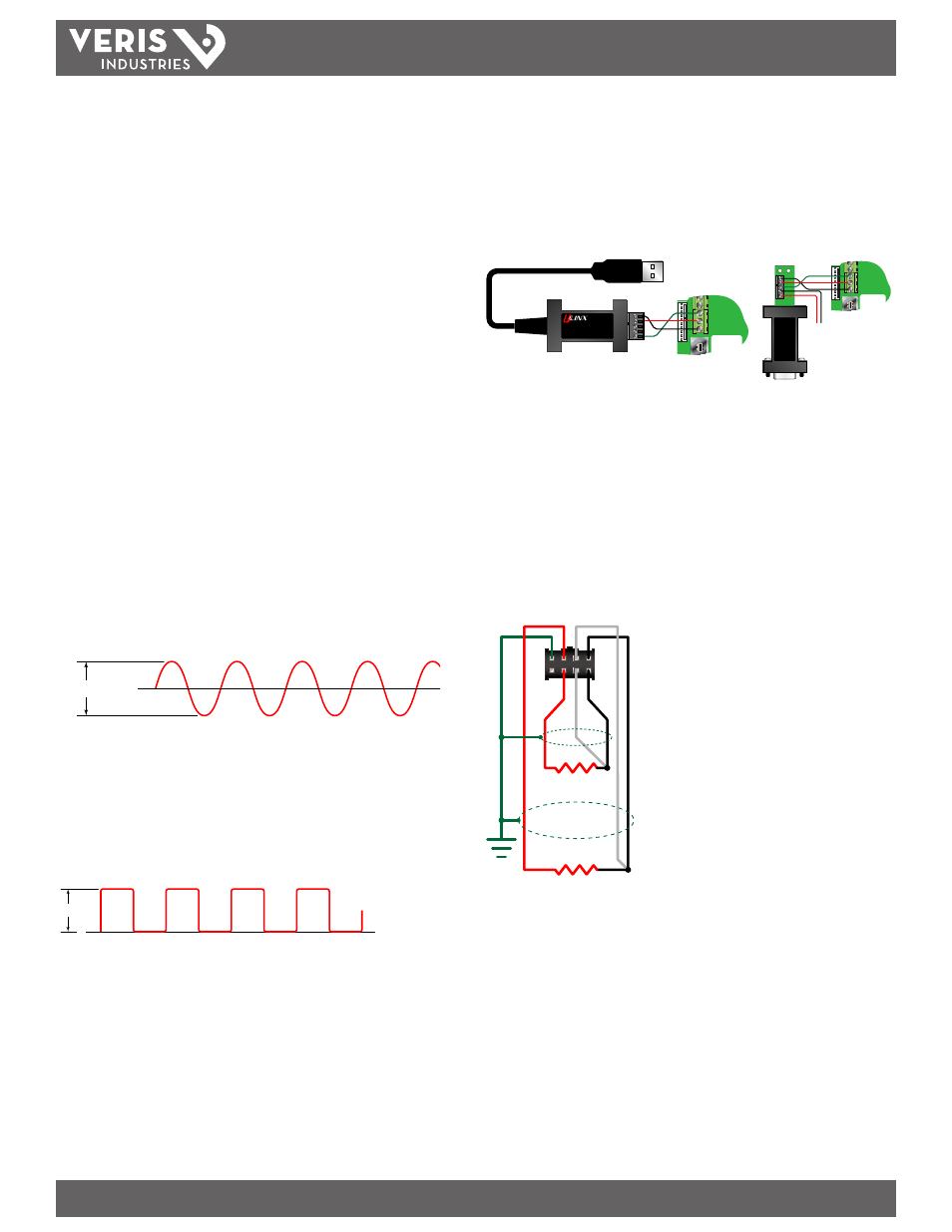
To interconnect meters, utilize three-wire shielded cable such as Belden® 9939 or
equal. In noisy environments, connect the shield on one end to earth ground. Use a
USB to RS-485 converter to communicate with a PC running Windows 98, Windows
ME, Windows 2000, Windows NT, Windows XP, Windows Vista, or Windows 7.
For computers with RS-232C serial ports, use an RS-232C to RS-485 converter to
interconnect the RS-485 network to a communication port on a PC. If monitoring
more than 126 meters, use an additional converter and communication port.
4-20 mA Out
Reset Total
Modbus Gnd
Modbus B
Modbus A
Model 485USBTB-2W
A (-)
B (+)
A (-)
B (+)
GND
USB to RS485
4-20 mA Out
Reset Total
Modbus Gnd
Modbus B
Modbus A
TD(A)-
TD(B)+
GND
GND
+12V
RS
-485 C
on
ver
ter
M
odel 485SD9TB
RS-232
RS-485
To 12 VDC
Supply
RS232 to RS485
Figure 3.9 - RS-485 Network Connections
Heat Flow [BTU meters only]
The BTU meter allows the integration of two 1000 Ω, 3-wire, platinum RTDs with the
flow meter, providing a means of measuring energy consumed in liquid heating and
cooling systems. The RTDs are attached at the factory to a simple plug-in connector
eliminating the possibility of mis-wiring. Simply install the RTDs on or in the pipe as
recommended, and then plug the RTDs into the meter. The surface mount versions
are available in standard lengths of 20 feet (6 meters), 50 feet (15 meters) and 100
feet (30 meters) of attached shielded cable.
1000 Ω
1000 Ω
SUPPLY LINE
RTD #1
RETURN LINE
RTD #2
BACK OF
CONNECTOR
Figure 3.10 - RTD Schematic
Installation of Surface Mount RTDs
Only use surface mount RTDs on well insulated pipe. Installing the RTD in an
uninsulated area causes inconsistent temperature readings.
Select areas on the supply and return pipes to mount the RTDs. Remove or peel back
the insulation all the way around the pipe in the installation area. Clean an area
slightly larger than the RTD down to bare metal on the pipe.
Place a small amount of heat sink compound on the pipe in the RTD installation
location. See Figure 3.11. Press the RTD firmly into the compound. Fasten the RTD to
the pipe with the included stretch tape.
Frequency Output [FSRxxx1x only]
The frequency output is an open-collector transistor circuit that outputs a pulse
waveform that varies proportionally with flow rate. This type of frequency output is
also know as a “Rate Pulse” output. The frequency output is proportional to the max
flow rate entered into the meter. The maximum output frequency is 1000 Hz.
In addition to the control outputs, the frequency output can be used to provide total
information by use of a K-factor that relates the number of pulses from the frequency
output to the number of accumulated pulses that equates to a specific volume.
This relationship is described by the following equation: K-factor = 60,000 / full scale
units. The 60,000 relates to measurement units in volume/min. Measurement units in
seconds, hours or days would require a different numerator.
If the frequency output is to be used as a totalizing output, then the meter and the
receiving instrument must have identical K-factor values programmed into them
to ensure that accurate readings are recorded by the receiving instrument. Unlike
standard mechanical flow meters such as turbines, gear or nutating disk meters, the
K-factor can be changed by modifying the MAX RATE flow rate value.
Note: For a full treatment of K-factors please see the Appendix of this manual.
There are two frequency output types available:
1.) Turbine meter simulation - This option is utilized when a receiving
instrument is capable of interfacing directly with a turbine flow meter’s
magnetic pickup. The output is a relatively low voltage AC signal whose
amplitude swings above and below the signal ground reference. The
minimum AC amplitude is approximately 500 mV peak-to-peak. To activate
the turbine output circuit, turn SW4 OFF .
0
500 mV
p-p
Figure 3.7 - Frequency Output Waveform (Simulated Turbine)
2.) Square-wave frequency - This option is utilized when a receiving
instrument requires that the pulse voltage level be either of a higher
potential and/or referenced to DC ground. The output is a square-wave with
a peak voltage equaling the instrument supply voltage when the SW3 is ON.
If desired, an external pull-up resistor and power source can be utilized by
leaving SW3 OFF. Set SW4 to ON for a square-wave output.
0
+V
Figure 3.8 - Frequency Output Waveform (Square Wave)
RS-485
The RS-485 feature allows up to 126 metering systems to be placed on a single three-
wire cable bus. Each meter is assigned a unique numeric address that allows all of the
meters on the cable network to be independently accessed. A Modbus RTU command
protocol is used to interrogate the meters. An explanation of the command structure
is detailed in the APPENDIX of this manual. Flow rate, total, signal strength and
temperature (if so equipped) can be monitored over the digital communications bus.
Baud rates up to 9600 and cable lengths to 5,000 feet (1,500 meters) are supported
without repeaters or “end of line” resistors.