Installation guide, Small pipe transducer installation – Veris Industries FSRxxxx SERIES Install User Manual
Page 12
FSRxxxx SERIES
Z205739-0D
PAGE 12
©2013 Veris Industries USA 800.354.8556 or +1.503.598.4564 / [email protected]
05131
Alta Labs, Enercept, Enspector, Hawkeye, Trustat, Aerospond, Veris, and the Veris ‘V’ logo are trademarks or registered trademarks of Veris Industries, L.L.C. in the USA and/or other countries.
TM
INSTALLATION GUIDE
Transducer Positioning
1. Place the upstream transducer in position and secure with a mounting strap. Place
straps in the arched groove on the end of the transducer. A screw is provided to
help hold the transducer onto the strap. Tighten the transducer strap securely.
2. Place the downstream transducer on the pipe at the calculated transducer spacing.
See Figure 2.5. Apply firm hand pressure. If signal strength is greater than 5,
secure the transducer at this location. If the signal strength is not 5 or greater
then using firm hand pressure, slowly move the transducer both towards and
away from the upstream transducer while observing signal strength. Clamp
thetransducer where the highest signal strength is observed. Signal levels much
less than 5 may not yield acceptable data.
Note: Signal strength readings update only every few seconds, so it is advisable to move
the transducer 1/8”, wait, see if signal is increasing or decreasing and then repeat until
the highest level is achieved.
3. If after adjustment of the transducers the signal strength does not rise to above 5,
then select an alternate transducer mounting method. If the mounting method
was W-Mount, then re-configure the monitor for V-Mount, move the downstream
transducer to the new spacing distance and repeat Step 4.
Transducer
Spacing
Figure 2.5 - Transducer Positioning
Small Pipe Transducer Installation
The small pipe transducers are designed for specific pipe outside diameters. Do not
attempt to mount a transducer onto a pipe that is either too large or too small for the
transducer.
FST1, FST2, and FST3 installation consists of the following steps:
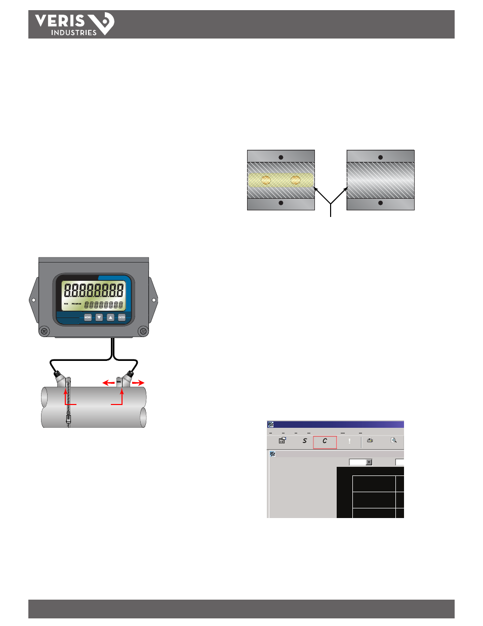
1. Apply a thin coating of acoustic coupling grease to both halves of the transducer
housing where the housing will contact the pipe. See Figure 2.6.
1/16” (1.5 mm)
Acoustic Couplant Grease
Figure 2.6 - Application of Acoustic Couplant — FST1, FST2, FST3 Transducers
2. On horizontal pipes, mount the transducer in an orientation such that the cable
exits at ±45 degrees from the side of the pipe. Do not mount with the cable
exiting on either the top or bottom of the pipe. On vertical pipes the orientation
does not matter. See Figure 2.2.
3. Tighten the wing nuts or “U” bolts so that the acoustic coupling grease begins to
flow out from the edges of the transducer or from the gap between the transducer
halves. Do not over tighten.
4. If signal strength is less than 5, remount the transducer at another location on the
piping system.
5. Configuration Procedure:
a. Establish communications with the transit tme meter. See Part 5 -
Software Utility.
b. From the tool bar, select calibration.
Device Addr 127
Flow:
Totalizer Net:
Pos:
Neg:
Sig. Strength:
Margin:
Delta T:
Last Update:
Help
Window
Communications
View
Edit
File
Print Previe
1350 Gal/Min
0 OB
15.6%
100%
-2.50 ns
09:53:39
0 OB
0 OB
Errors
rro
!
Configuration
Calibration
Strategy
1600
2000
1200
Scale:
60 Min
Time:
200
USP - Device Addr 127
c. On the pop-up screen, click Next twice to get to page 3 of 3. Click Edit in this
screen.