Installation guide, Flow tab, Filtering tab – Veris Industries FSRxxxx SERIES Install User Manual
Page 30: Figure 5.3 - flow tab, Figure 5.4 - filtering tab
FSRxxxx SERIES
Z205739-0D
PAGE 30
©2013 Veris Industries USA 800.354.8556 or +1.503.598.4564 / [email protected]
05131
Alta Labs, Enercept, Enspector, Hawkeye, Trustat, Aerospond, Veris, and the Veris ‘V’ logo are trademarks or registered trademarks of Veris Industries, L.L.C. in the USA and/or other countries.
TM
INSTALLATION GUIDE
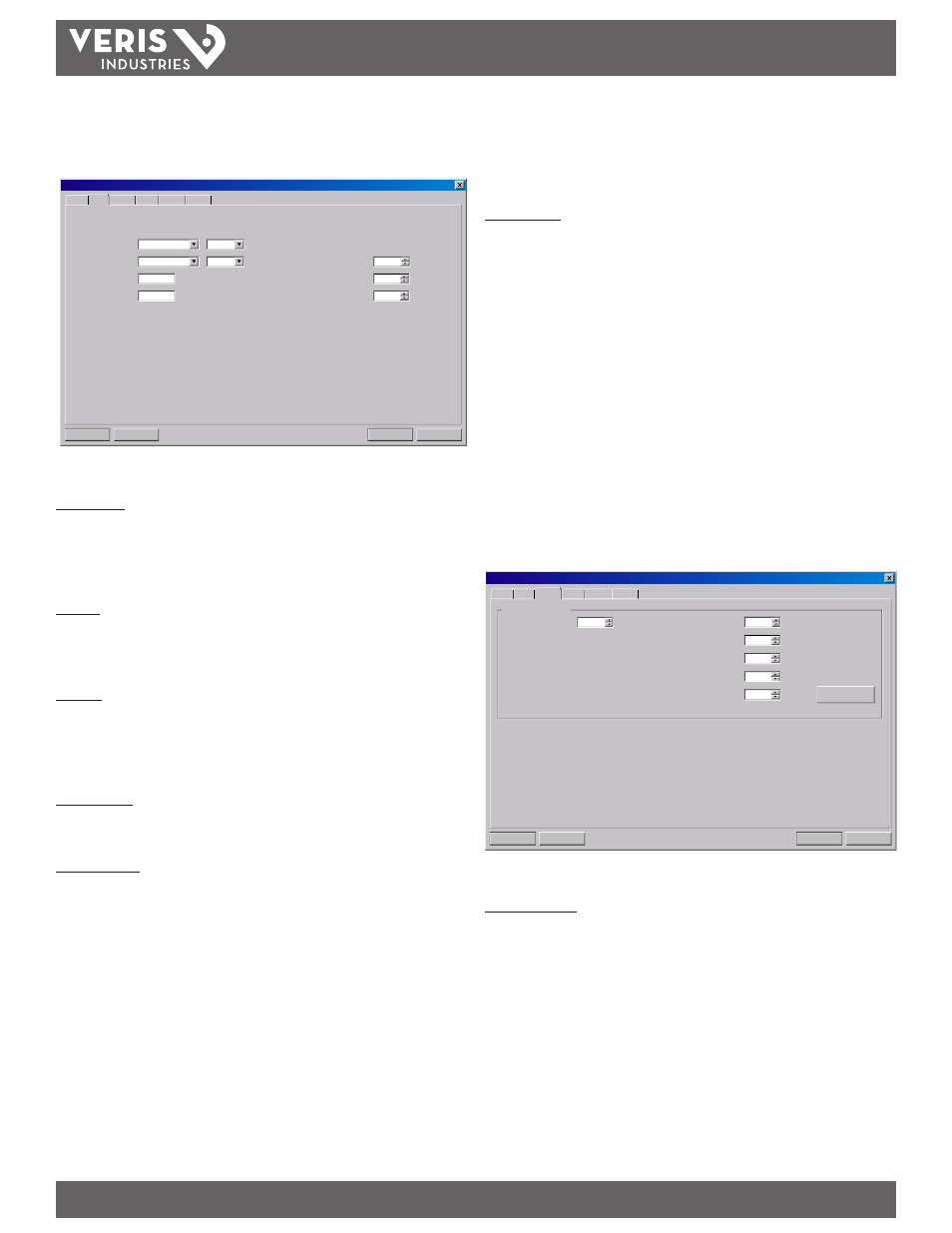
Flow Tab
Select flow rate units and a flow rate interval from the drop-down lists.
Download
Cancel
File Open...
File Save...
System Configuration
Display
Basic Flow Filtering Output Security
Gallons
Min
Flow Rate Units:
/
Gallons
X10
Totalizer Units:
0.0
Min Flow:
Gal/M
Gal/M
400.0
Max Flow:
Low Flow Cutoff:
Low Signal Cutoff:
%
%
Substitute Flow:
2
2
0
Figure 5.3 - Flow Tab
Totalizer Units are selected from drop-down lists. Select an appropriate totalizer unit
and totalizer exponent. The totalizer exponents are in scientific notation and permit
the eight digit totalizer to accumulate very large values before the totalizer “rolls
over” and starts again at zero. Table 4.4 illustrates the scientific notation values and
their respective decimal equivalents.
Min Flow is the minimum volumetric flow rate to establish filtering parameters.
Volumetric entries are in the flow rate units. For unidirectional measurements,
set Min Flow to zero. For bidirectional measurements, set Min Flow to the highest
negative (reverse) flow rate expected in the piping system.
Max Flow is the maximum volumetric flow rate to establish filtering parameters.
Volumetric entries are in the Flow Rate Units. For unidirectional measurements,
set Max Flow to the highest (positive) flow rate expected in the piping system.
For bidirectional measurements, set Max Flow to the highest (positive) flow rate
expected in the piping system.
Low Flow Cutoff is provided to allow very low flow rates (present when pumps are off
and valves are closed) to be displayed as zero flow. Typical values that are between
1.0% and 5.0% of the flow range between Min Flow and Max Flow.
Low Signal Cutoff is used to drive the flow meter and its outputs to the value
specified in the Substitute Flow field when conditions occur that cause low signal
strength. A signal strength below 5 is inadequate for measuring flow reliably, so the
minimum setting for Low Signal Cutoff is 5. A good practice is to set the Low Signal
Cutoff at approximately 60-70% of actual measured maximum signal strength.
Note: The factory default “Low Signal Cutoff” is 5.
If the measured signal strength is lower than the Low Signal Cutoff setting, a “Signal
Strength too Low” highlighted in red appears in the text area to the left in the Data
Display screen until the measured signal strength becomes greater than the cutoff
value.
Signal strength indication below 2 is considered to be no signal at all. Verify that the
pipe is full of liquid, the pipe size and liquid parameters are entered correctly, and the
transducers are mounted accurately. Highly aerated liquids cause low signal strength
conditions.
Substitute Flow is a value that the analog outputs and the flow rate display show to
indicate that an error condition in the flow meter has occured.
Substitute Flow is set as a percentage between Min Flow and Max Flow. In a
unidirectional system, this value is typically set to zero to indicate zero flow while
in an error condition. To calculate where to set the Substitute Flow value in a
bidirectional system, perform the following operation:
Substitute Flow = 100 - (100
×
max. flow) / (max. flow - min. flow)
Entry of data in the Basic and Flow tabs is all that is required to provide flow
measurement functions to the flow meter. If the user is not going to utilize input/
output functions, click on the Download button to transfer the configuration to the
meter. When the configuration has been completely downloaded, power cycle the
meter to guarantee the changes take effect.
Filtering Tab
The Filtering tab contains several filter settings for the flow meter. These filters
can be adjusted to match response times and data “smoothing” performance to a
particular application.
Download
Cancel
File Open...
File Save...
System Configuration
Display
Basic Flow Filtering Output Security
%
Flow Filter (Damping):
%
80
Time Domain Filter:
8
Advanced Filter Settings:
Flow Filter Hystersis:
5
psec
Flow Filter Min Hystersis:
303
Bad Data Rejection:
3
Flow Filter Sensitivigy:
3
Factory Defaults
Figure 5.4 - Filtering Tab
Time Domain Filter (range 1-256) adjusts the number of raw data sets (the wave
forms viewed on the software Diagnostics Screen) that are averaged together.
Increasing this value provides greater damping of the data. Conversely, lowering this
value decreases the response time of the meter to changes in flow/energy rate.
Note: The meter completes a measurement in approximately 350-400 msec. The exact time is pipe
size dependant.