Installation guide, Part 5 - software utility, Introduction – Veris Industries FSRxxxx SERIES Install User Manual
Page 28: System requirements, Installation, Initialization, Basic tab, Figure 5.1 - data display screen, Figure 5.2 - basic tab
FSRxxxx SERIES
Z205739-0D
PAGE 28
©2013 Veris Industries USA 800.354.8556 or +1.503.598.4564 / [email protected]
05131
Alta Labs, Enercept, Enspector, Hawkeye, Trustat, Aerospond, Veris, and the Veris ‘V’ logo are trademarks or registered trademarks of Veris Industries, L.L.C. in the USA and/or other countries.
TM
INSTALLATION GUIDE
PART 5 - SOFTWARE UTILITY
Note: Outputs are disabled when the meter is connected to a computer through the software
utility.
Introduction
In addition to the keypad entry programming, the flow meter can be used with
a software utility. The software utility is used for configuring, calibrating and
communicating with the meter. Additionally, it has numerous troubleshooting tools
to make diagnosing and correcting installation problems easier. Hard-wire a PC to a
flow meter through a standard USB connection.
System Requirements
The software requires a PC-type computer running Windows 98, Windows ME,
Windows 2000, Windows NT, Windows XP, Windows Vista®, or Windows 7 operating
systems and a USB communications port.
Installation
1. From the Windows “Start” button choose the Run command. From the “Run”
dialog box use the Browse button to navigate to the USP_Setup.exe file and
double-click.
2. The USP Setup automatically extracts and installs on the hard disk. The USP icon
can then be copied to the desktop, if desired.
Note: If a previous version of this software is installed, un-install it before installing the new
version. Newer versions “ask” to remove the old version and perform the task automatically. Older
versions must be removed using the Microsoft Windows® Add/Remove Programs applet.
Initialization
1. Connect the B end of the USB A/B communications cable to the USB
communication port on the meter and the A end to a convenient USB port on the
computer.
Note: It is advisable to have the meter powered up prior to running this software.
Note: While the USB cable is connected to a computer, the RS-485 and frequency outputs are
disabled.
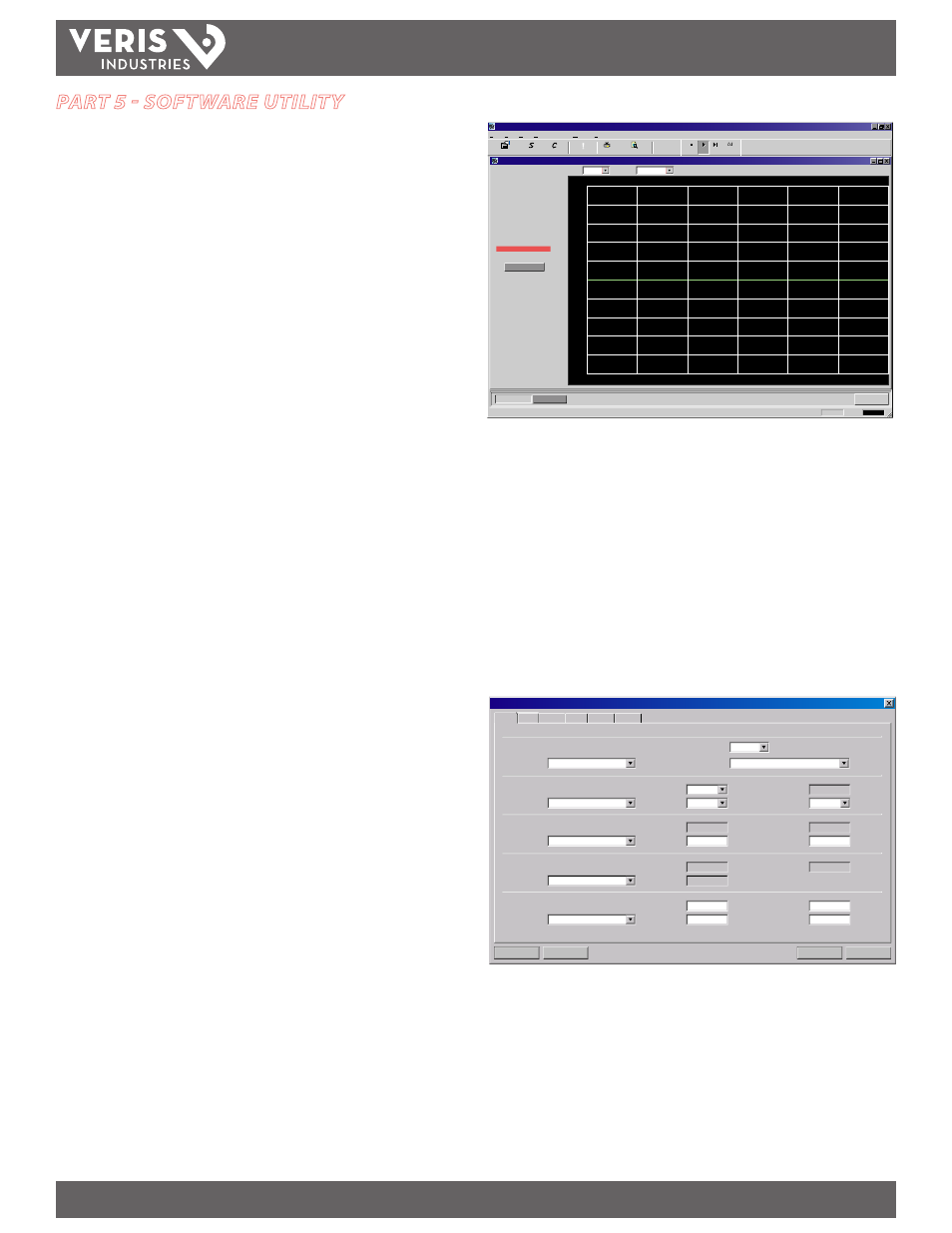
2. Double-click on the USP icon. The first screen is the “RUN” mode screen (see Figure
5.1), which contains real-time information regarding flow rate, totals, signal
strength, communications status, and the flow meter’s serial number. The COMM
indicator in the lower right-hand corner indicates that the serial connection is
active. If the COMM box contains a red ERROR, click on the Communications button
on the Menu bar and select Initialize. Choose the appropriate COM port and the
RS-232/USB Com Port Type. A green “OK” in the lower right-hand corner of the PC
display and verifies proper communication. The “Last Update” indicator in the text
area on the left side of the screen changes from red to an active clock indication.
USP - Device Addr 127
Data Display
Diagnostics
Device Addr 127
Reset Totalizers
About
Window
Communications
View
Edit
File
About
?
?
Errors
!
Configuration
Calibration
Strategy
Exit
OK
13:26:33 COMM:
USP
Go
Stop
Stop
Stop
Step View
-1.00:00
-2000
-1600
1600
-1200
-800
-400
2000
1200
800
400
0
-50:00
-40:00
-30:00
-20:00
-10:00
-0:00
Time (mm:ss)
Flow Rate
Historical Data
Scale:
Time: 60 Min
2000
135 Gal/Min
237 Gal
15.6%
100%
2.50 ns
Flow:
Totalizer Net:
Pos:
Neg:
Sig. Strength:
Margin:
Delta T:
Last Update: 12:17:20
0 Gal
237 Gal
Print Preview
Signal Strength too Low!
Figure 5.1 - Data Display Screen
The Configuration drop-down houses six screens used to control how the meter is
set up and responds to varying flow conditions. The first screen that appears after
clicking the Configuration button is the Basic screen See Figure 5.2.
Basic Tab
1. General
The general heading allows users to select the measurement system for meter setup,
either English or Metric, and choose from a number of pre-programmed small pipe
configurations in the Standard Configurations drop-down. If the General entries are
altered from those at instrument start-up, then click on the Download button in the
lower right-hand portion of the screen and cycle power to the meter.
Download
Cancel
File Open...
File Save...
System Configuration
Flow
Basic
Display
Basic
Flow Filtering Output Security
DTTN Clamp-On
Z
1 MHz
1.33 in
Forward
Carbon Steel
10598.00
1.5
0.000150
0.218
Other
1
1
8061
1
None
0.0
0.0
0.0
English
Custom
7
General
Transducer
Pipe
Liner
Fluid
Units:
Type:
Material:
Material:
Standard Configurations:
MODBUS Address:
Flow Direction:
Wall Thickness:
in
cp
FPS
in
in
FPS
FPS
Type:
Frequency:
Pipe OD:
Thickness:
Spec. Gravity:
Sound Speed:
Sound Speed:
Sound Speed:
Mount:
Spec. Heat Capacity:
Abs. Viscosity:
Roughness:
Roughness:
Spacing:
Figure 5.2 - Basic Tab