Installation guide, Heating and cooling measurement, Cp where: q = volumetric flow rate t – Veris Industries FSRxxxx SERIES Install User Manual
Page 44: Temperature at the inlet t
FSRxxxx SERIES
Z205739-0D
PAGE 44
©2013 Veris Industries USA 800.354.8556 or +1.503.598.4564 / [email protected]
05131
Alta Labs, Enercept, Enspector, Hawkeye, Trustat, Aerospond, Veris, and the Veris ‘V’ logo are trademarks or registered trademarks of Veris Industries, L.L.C. in the USA and/or other countries.
TM
INSTALLATION GUIDE
Heating and Cooling Measurement
The FSR2xxxx energy meter is designed to measure the rate and quantity of heat
delivered to a given building, area or heat exchanger. The instrument measures the
volumetric flow rate of the heat exchanger liquid (water, water/glycol mixture, brine,
etc.), the temperature at the inlet pipe, and the temperature at the outlet pipe. Heat
delivery is calculated by the following equation:
Rate of heat delivery = Q
×
(T
in
- T
out
)
×
Cp
Where:
Q = volumetric flow rate
T
in
= temperature at the inlet
T
out
= temperature at the outlet
Cp = specific heat of the liquid
The RTD temperature measurement circuit in the meter measures the differential
temperature of two 1,000 Ω, three-wire platinum RTDs. The three-wire configuration
allows the temperature sensors to be located several hundred feet away from the
meter without influencing system accuracy or stability.
The energy meter allows integration of two 1,000 Ω platinum RTDs with the flow
meter, effectively providing an instrument for measuring energy delivered in liquid
cooling and heating systems. If RTDs were ordered with the flow meter, they have
been factory calibrated and are shipped connected to the module as they were
calibrated.
Field replacement of RTDs is possible thru the use of the keypad or the software
utility. If the RTDs were ordered from the manufacturer, they will come with
calibration values that need to be loaded into the meter.
New, non-calibrated RTDs will need to be field calibrated using an ice bath and
boiling water to derive calibration values. This procedure is outlined below.
In Field Calibration of RTD Temperature Sensors
Replacement RTD temperature sensors used in heat flow measurements must be
calibrated in the field to ensure proper operation. Failure to calibrate the RTDs to the
specific BTU inputs will result in inaccurate heat flow measurements.
Equipment Required:
Ice Bath
Boiling Water Bath
Laboratory Grade Thermometer (accurate to 0.1 °C)
Software Utility
Replacing or Re-calibrating RTDs
This procedure works with pairs of surface mount RTDs or pairs of insertion RTDs
supplied by the manufacturer.
1. Connect the RTDs
2. Establish communications with the flow meter using the software utility.
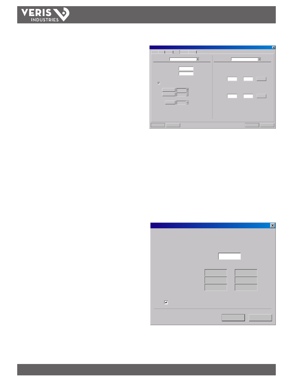
3. Click on the “Configuration” tab in the menu bar and then select the “Output” tab.
The screen should now look something like the following.
Download
Cancel
File Open...
File Save...
System Configuration
Display
Basic
Flow Filtering Output Security
4-20mA / Frequency
Channel 1:
0
Flow at 4mA / 0Hz:
Gal/M
400
Flow at 20mA / 1KHz:
Gal/M
Calibration/Test
Test
Calibration
4 mA
20 mA
32
3837
Test
4
RTD
Channel 2:
RTD #1:
A:
B:
Calibrate
0.0000
0.0000
RTD #2:
A:
B:
Calibrate
0.0000
0.0000
Figure A-4.1 - Output Configuration Screen
4. If “RTD” is not selected in the Channel 2 drop-down list, select it now.
5. Insert both RTD temperature sensors and the laboratory grade thermometer into
either the ice bath or the boiling water bath and allow about 20 minutes for the
sensors to come up to the same temperature.
Note: An ice bath and boiling water bath are used in these examples because their temperatures
are easy to maintain and provide known temperature reference points. Other temperature
references can be used as long as there is a minimum delta T of 40 °C between the two references.
6. Click on the “Calibrate” button and the following screen should now be visible.
Make sure that the “Calibrate Both RTDs at same temperature” box is checked and
then enter the temperature to the nearest 0.1 °C in the box labeled “Reference
Temp (deg C)”
DAC Value:
Calibrated Temp (deg C):
Calibrated Temp (deg F):
First Cal Point
Reference Temp (deg C):
RTD 1
RTD 2
Calibrate RTD 1, or select the checkbox below to calibrate both RTDs at the same
temperature. Make sure that the RTD is at a known temperature and enter this
temperature below:
Calibrate Both RTDs at same temperature
RTD Calibration (Step 1 of 2)
OK
Cancel
1
0.0 °C
32.0 °F
3
0.0 °C
32.0 °F
Figure A-4.2 - RTD Calibration (Step 1 of 2)
7. Press “Next”
8. Repeat this process with the second water bath.