Installation guide, Part 3 - inputs/outputs, Operate in the shaded regions – Veris Industries FSRxxxx SERIES Install User Manual
Page 14
FSRxxxx SERIES
Z205739-0D
PAGE 14
©2013 Veris Industries USA 800.354.8556 or +1.503.598.4564 / [email protected]
05131
Alta Labs, Enercept, Enspector, Hawkeye, Trustat, Aerospond, Veris, and the Veris ‘V’ logo are trademarks or registered trademarks of Veris Industries, L.L.C. in the USA and/or other countries.
TM
INSTALLATION GUIDE
90-265 VAC
AC Neutral
Control 1
Control 2
Frequency Out
4-20 mA Out
Reset Total
Signal Gnd.
Meter Power
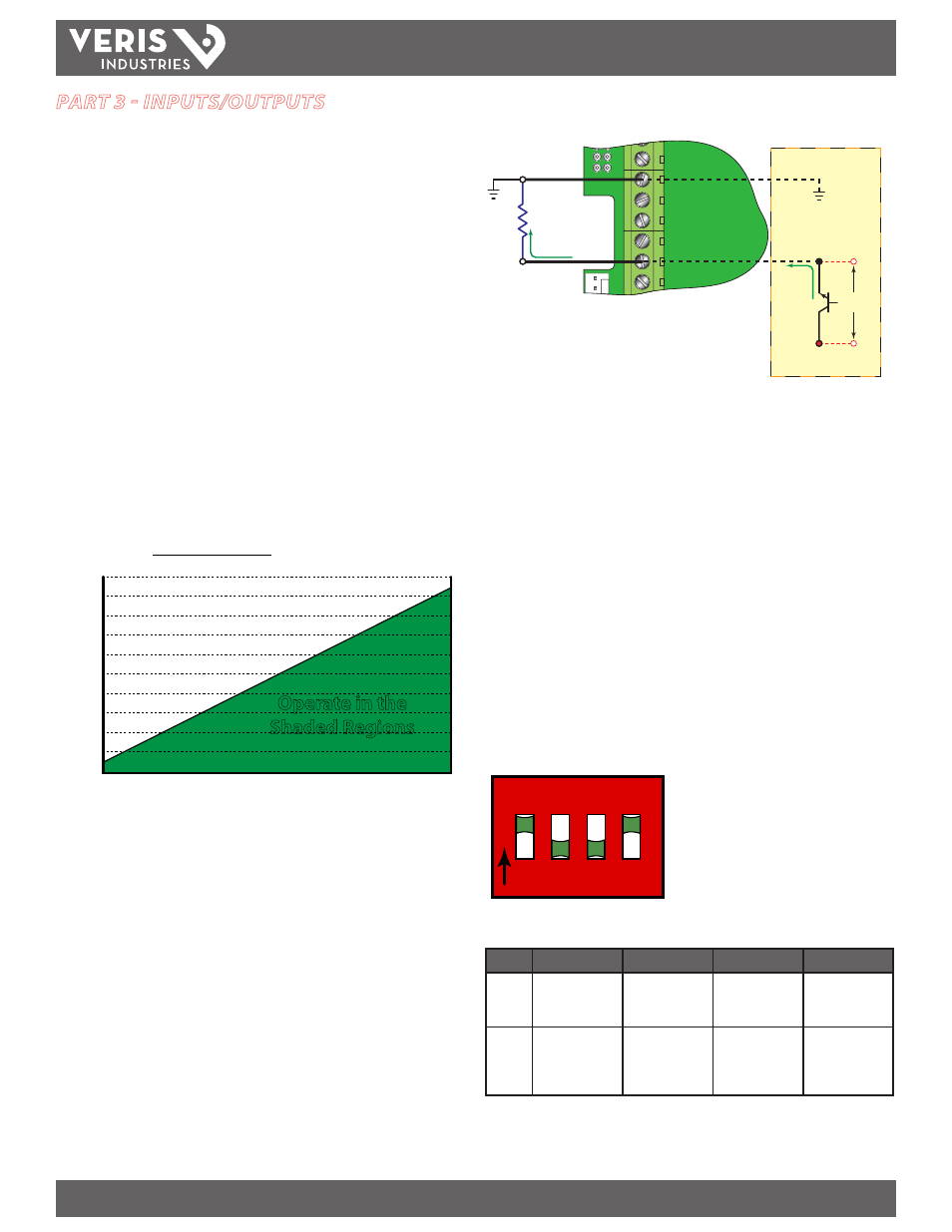
Loop
Resistance
Signal Ground
7 VDC
Drop
Figure 3.2 - 4-20 mA Output
The 4-20 mA output signal is available between the 4-20 mA Out and Signal Gnd.
terminals as shown in Figure 3.2.
Control Outputs
Two independent open collector transistor outputs are included with the flow meter.
Each output can be configured for one of the following four functions:
Rate Alarm
Signal Strength Alarm
Totalizing/Totalizing Pulse
Errors
None
Both control outputs are rated for a maximum of 100 mA and 10 to 28 VDC. A pull-up
resistor can be added externally or an internal 10 kΩ pull-up resistor can be selected
using DIP switches on the power supply board.
1 2 3 4
O
N
Figure 3.3 - Switch Settings
Switch
S1
S2
S3
S4
On
Control 1 pull-up;
Resistor IN circuit
Control 2 pull-up;
Resistor IN circuit
Frequency output
pull-up;
Resistor IN circuit
Square wave
output
Off
Control 1 pull-up;
Resistor OUT OF
circuit
Control 2 pull-up;
Resistor OUT OF
circuit
Frequency output
pull-up;
Resistor OUT OF
circuit
Simulated turbine
output
Table 3.1 - DIP Switch Functions
PART 3 - INPUTS/OUTPUTS
General
The FSR1 is available in two configurations: the flow model and the energy model.
The flow model is equipped with a 4-20 mA output, two open collector outputs, a
rate frequency output, and RS-485 communications using the Modbus RTU command
set. The energy version has inputs for two 1,000 Ω RTD sensors in place of the rate
frequency and alarm outputs. This version allows the measurement of pipe input and
output temperatures for calculating energy usage calculations.
4-20 mA Output
The 4-20 mA output interfaces with most recording and logging systems by
transmitting an analog current signal that is proportional to system flow rate. The
4-20 mA output is internally powered (current sourcing) and can span negative to
positive flow/energy rates.
For AC powered units, the 4-20 mA output is driven from a +15 VDC source located
within the meter, isolated from earth ground connections. The AC powered model
accommodates loop loads up to 400 Ω. DC powered meters utilize the DC power
supply voltage to drive the current loop. The current loop is not isolated from DC
ground or power. Figure 3.1 shows graphically the allowable loads for various input
voltages. The combination of input voltage and loop load must stay within the
shaded area of Figure 3.1.
200
100
300
400
500
600
700
800
900
1000
1100
10
12
14
16
18
20
22
24
26
28
Supply Voltage (VDC)
Lo
op L
oad (
O
hms)
Operate in the
Shaded Regions
Supply Voltage - 7 VDC
0.02
= Maximum Loop Resistance
Figure 3.1 - Allowable Loop Resistance (DC Powered Units)