Installation guide – Veris Industries FSRxxxx SERIES Install User Manual
Page 50
FSRxxxx SERIES
Z205739-0D
PAGE 50
©2013 Veris Industries USA 800.354.8556 or +1.503.598.4564 / [email protected]
05131
Alta Labs, Enercept, Enspector, Hawkeye, Trustat, Aerospond, Veris, and the Veris ‘V’ logo are trademarks or registered trademarks of Veris Industries, L.L.C. in the USA and/or other countries.
TM
INSTALLATION GUIDE
*
Substitute part must be suitable for Class I, II, Div 2, Groups C, D.
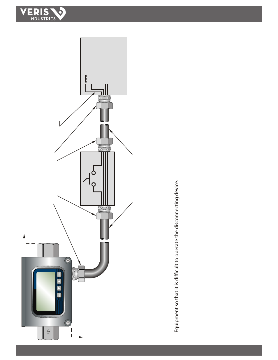
DC POWERED
HAZARDOUS
AREA
INSTALLATION
NAME:
1.
Information shown on this drawing is provided to indicate wiring requirements to comply with National Electrical Code
®
(NEC) Article 500.
2.
Disconnect to be located near the Flow meter. Do not position the
3.
Disconnect may not be required if Flow meter is powered from a class 2 Power Supply.
4.
Smaller gauge wire may be acceptable if overall system meets NEC requirements per Article 725 Part III.
TO
:
RATE PULSE, TOT
AL PULSE,
4-20mA,
TOTAL
RESET
OR RS485 I/O IF USED
10 - 28 VDC
Ø VDC
USER EQUIPMENT
DISCONNECT
( NOTE 2,3 )
OFF
ON
ANACONDA SEALTITE
TYPE UA-1/2 FLEXIBLE CONDUIT
OR EQUIVALENT
*
CROUSE-HINDS
CONDUIT CONNECTOR
OR EQUIVALENT
*
BY OTHERS
BY
O
TH
ER
S
FLOW METER
WIRE USED TO BE 14 GA, 60ºC, 600V
( NOTE 4 )
+ DC
+ DC
Fig
ur
e A
-6
.4 - H
az
ar
do
us A
rea I
ns
ta
lla
tio
n