Danger, Installation guide, Introduction – Veris Industries FSRxxxx SERIES Install User Manual
Page 6: Hazard of electric shock, explosion, or arc flash
FSRxxxx SERIES
Z205739-0D
PAGE 6
©2013 Veris Industries USA 800.354.8556 or +1.503.598.4564 / [email protected]
05131
Alta Labs, Enercept, Enspector, Hawkeye, Trustat, Aerospond, Veris, and the Veris ‘V’ logo are trademarks or registered trademarks of Veris Industries, L.L.C. in the USA and/or other countries.
TM
INSTALLATION GUIDE
Because the transducers are non-contacting and have no moving parts, the flow
meter is not affected by system pressure, fouling, or wear. FST4 and FST5 transducers
are rated to a pipe surface temperature of -40 to +250 °F (-40 to +121 °C). FST1, FST2,
and FST3 small pipe transducers are rated from -40 to +185 °F (-40 to +85 °C).
Frequency
Transducers
Transmission
Modes
Pipe Size and
Type
2 MHz
All ½” thru 1½”
2” Tubing
Selected by
Firmware
Specific to
Transducer
1 MHz
2” ANSI and Copper
Selected by
Firmware
Specific to
Transducer
all 2” to 24”
W, V, and Z
2” to 24”
500 kHz
larger than 24”
W, V, and Z
24” and Greater
User Safety
The FSR Series employs modular construction and provides electrical safety for the
operator. The display face contains voltages no greater than 28 VDC. The display face
swings open to allow access to user connections.
DANGER
HAZARD OF ELECTRIC SHOCK, EXPLOSION, OR ARC FLASH
• Disconnect electrical power before opening the instrument enclosure.
• Wiring must conform to applicable codes.
Failure to follow these instructions will result in death or serious injury.
Data Integrity
Non-volatile flash memory retains all user-entered configuration values in memory
for several years at 77°F (25°C), even if power is lost or turned off. Password
protection is provided as part of the Security menu (SEC MENU) and prevents
inadvertent configuration changes or totalizer resets.
Product Identification
The serial number and complete model number of the monitor are located on the top
outside surface of the housing. If technical assistance is required, please provide the
Customer Service Department with this information.
INTRODUCTION
General
The Veris ultrasonic flow meter is designed to measure the fluid velocity of liquid
within a closed conduit. The transducers are a non-contacting clamp-on or clamp-
around type that does not foul and is easy to install.
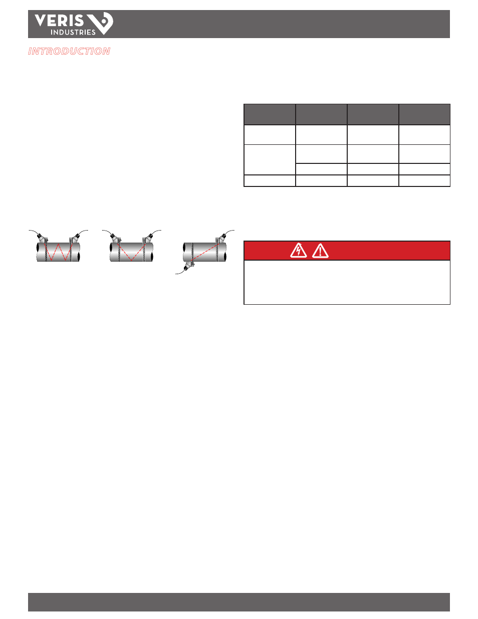
The Veris family of transit time flow meters utilize two transducers that function
as both ultrasonic transmitters and receivers. The transducers are clamped on
the outside of a closed pipe at a specific distance from each other. The transducers
can be mounted in V-Mount where the sound transverses the pipe two times,
W-Mount where the sound transverses the pipe four times, or in Z-Mount where the
transducers are mounted on opposite sides of the pipe and the sound crosses the pipe
once. The selection of mounting method is based on pipe and liquid characteristics
that both have an effect on how much signal is generated. The flow meter operates
by alternately transmitting and receiving a frequency modulated burst of sound
energy between the two transducers and measuring the time interval that it takes
for sound to travel between the two transducers. The difference in the time interval
measured is directly related to the velocity of the liquid in the pipe.
TOP VIEW
OF PIPE
TOP VIEW
OF PIPE
TOP VIEW
OF PIPE
W-Mount
V-Mount
Z-Mount
Figure 1.1 - Ultrasound Transmission
Application Versatility
The FSRxxxx flow meter can be successfully applied on a wide range of metering
applications. The simple-to-program monitor allows the standard product to be used
on pipe sizes ranging from ½ inch to 100 inches (12 mm to 2540 mm) pipe*. A variety
of liquid applications can be accommodated:
ultrapure liquids
potable water
chemicals
sewage
reclaimed water
cooling water
river water
plant effluent
others