Installation guide, Channel 2 - rtd configuration [btu model only, Figure 5.6 - channel 2 input (rtd) – Veris Industries FSRxxxx SERIES Install User Manual
Page 32
FSRxxxx SERIES
Z205739-0D
PAGE 32
©2013 Veris Industries USA 800.354.8556 or +1.503.598.4564 / [email protected]
05131
Alta Labs, Enercept, Enspector, Hawkeye, Trustat, Aerospond, Veris, and the Veris ‘V’ logo are trademarks or registered trademarks of Veris Industries, L.L.C. in the USA and/or other countries.
TM
INSTALLATION GUIDE
Example 2 - to span the 4-20 mA output from 0 GPM to +100 GPM with 12 mA being
50 GPM, set the Flow at 4 mA / 0 Hz and Flow at 20 mA / 1,000 inputs as follows:
Flow at 4 mA / 0 Hz = 0.0
Flow at 20 mA / 1,000 Hz = 100.0
For the non-BTU meter, in this instance, zero flow is represented by 0 Hz and 4 mA.
The full scale flow or 100 GPM is 1,000 Hz and 20 mA, and a midrange flow of 50 GPM
is expressed as 500 Hz and 12 mA.
The 4-20 mA output is factory calibrated and should not require adjustment. If small
adjustments to the DAC (Digital to Analog Converter) are needed, for instance if
adjustments due to the accumulation of line losses from long output cable lengths
are required, the Calibration 4 mA and Calibration 20 mA can be used.
Calibration 4 mA -- 4 mA DAC Calibration Entry (Value)
Calibration 20 mA-- 20 mA DAC Calibration Entry (Value)
The Calibration 4 mA and Calibration 20 mA entries allows fine adjustments to be
made to the “zero” and full scale of the 4-20 mA output. To adjust the outputs, an
ammeter or reliable reference connection to the 4-20 mA output must be present.
Note: Calibration of the 20 mA setting is conducted much the same way as the 4 mA adjustments.
Note: Do not use the Calibration 4 mA and Calibration 20 mA entries to set the 4-20 mA range.
Utilize Flow at 4 mA / 0 Hz and Flow at 20 mA / 1,000 Hz detailed above for this purpose.
• 4 mA Calibration Procedure:
1) Disconnect one side of the current loop and connect the ammeter in series
(disconnect either wire at the terminals labeled 4-20 mA Out or Signal Gnd).
2) Using the arrow keys, increase the numerical value to increase the current
in the loop to 4 mA. Decrease the value to decrease the current in the loop to
4 mA. Typical values range between 40-80 counts.
3) Reconnect the 4-20 mA output circuitry as required.
• 20 mA Calibration Procedure:
1) Disconnect one side of the current loop and connect the ammeter in series
(disconnect either wire at the terminals labeled 4-20 mA Out or Signal Gnd).
2) Using the arrow keys, increase the numerical value to increase the current
in the loop to 20 mA. Decrease the value to decrease the current in the loop to
20 mA. Typical values range between 3700-3900 counts.
3) Reconnect the 4-20 mA output circuitry as required.
• 4-20 Test -- 4-20 mA Output Test (Value)
Allows a simulated flow value to be sent from the 4-20 mA output. By
incrementing this value, the 4-20 mA output transmits the indicated current
value.
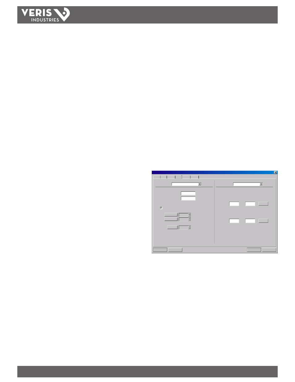
Channel 2 - RTD Configuration [BTU model only]
Note: The Channel 2 Menu is used to configure model specific I/O options. The non-BTU meter
presents a different set of parameters than the BTU meter.
Note: Choose the correct menu type for the meter in use. The software does not prohibit selecting
options pertaining only to the non-BTU meter when a BTU meter is present, and vice versa.
However, the outputs or meter readings will be unpredictable.
Inputs from two 1,000 Ω platinum RTD temperature sensors allow the measurement
of energy delivered in liquid heating and cooling systems.
The values used to calibrate the RTD temperature sensors are derived in the
laboratory and are specific to a specific RTD. The RTDs on new units come with the
calibration values already entered. Field replacement of RTDs is possible thru the use
of the keypad or the software. If the RTDs were ordered from the manufacturer, they
will come with calibration values that need to be loaded into the meter.
RTD Calibration Procedure:
1) Enter the calibration values for RTD #1 A and B followed by RTD #2 A and B.
2) Double-click on the Download button to send the values to memory.
3) Turn the meter power off and then back on to enable the changes to take
effect.
Download
Cancel
File Open...
File Save...
System Configuration
Display
Basic
Flow Filtering Output Security
4-20mA / Frequency
Channel 1:
0
Flow at 4mA / 0Hz:
Gal/M
400
Flow at 20mA / 1KHz:
Gal/M
Calibration/Test
Test
Calibration
4 mA
20 mA
32
3837
Test
4
RTD
Channel 2:
RTD #1:
A:
B:
Calibrate
0.0000
0.0000
RTD #2:
A:
B:
Calibrate
0.0000
0.0000
Figure 5.6 - Channel 2 Input (RTD)
New, non-calibrated RTDs need to be field calibrated using an ice bath and boiling
water to derive calibration values. This procedure is outlined in the Appendix of this
manual.