Installation guide, Setting zero and calibration, Figure 5.7 - channel 2 output choices – Veris Industries FSRxxxx SERIES Install User Manual
Page 33: Figure 5.8 - calibration page 1 of 3
FSRxxxx SERIES
Z205739-0D
PAGE 33
©2013 Veris Industries USA 800.354.8556 or +1.503.598.4564 / [email protected]
05131
Alta Labs, Enercept, Enspector, Hawkeye, Trustat, Aerospond, Veris, and the Veris ‘V’ logo are trademarks or registered trademarks of Veris Industries, L.L.C. in the USA and/or other countries.
TM
INSTALLATION GUIDE
Channel 2 - Control Output Configuration [FSR1 Only]
Two independent open collector transistor outputs are included with the non-BTU
flow meter. Each output can be configured independently to “Alarm” for one of the
following. See Alarm Output in Part 3 for output details.
None
Batch / Total
Flow
Signal Strength
Errors
Download
Cancel
File Open...
File Save...
System Configuration
Display
Basic
Flow Filtering Output Security
Control Outputs
Channel 2:
50
Off <
Gal/M
350
On>
Gal/M
Mode: Flow
Control 1
50
Off <
Gal/M
350
On>
Gal/M
Mode: Flow
Mode: None
Control 2
4-20mA / Frequency
Channel 1:
0
Flow at 4mA / 0Hz:
Gal/M
400
Flow at 20mA / 1KHz:
Gal/M
Calibration/Test
Test
Calibration
4 mA
20 mA
32
3837
Test
4
Flow
Batch/Total
Flow
Sig Strength
Errors
Control Outputs
Channel 2:
Figure 5.7 - Channel 2 Output Choices
None: All alarm outputs are disabled
Batch / Total: Multiplier (Value)
This is the value to which the totalizer accumulates before actuating the control pulse
output and repeating the accumulation. This value includes any exponents that were
entered in the BSC MENU as TOTAL E. See Alarm Output in Part 3
50
Multiplier:
Mode:
Batch/Total
Control 1
Flow
ON (Value): Sets value at which the alarm output will switch from OFF to ON
OFF (Value): Sets value at which the alarm output will switch from ON to OFF
50
Off <
Gal/M
350
On>
Gal/M
Mode:
Flow
Control 1
Signal Strength
ON (Value) : Sets value at which the alarm output will turn ON
OFF (Value): Sets value at which the alarm output will turn OFF
Off <
On>
Mode:
Sig Strength
Control 1
Errors
Alarm outputs on any error condition. See Error Table in the Appendix of this manual.
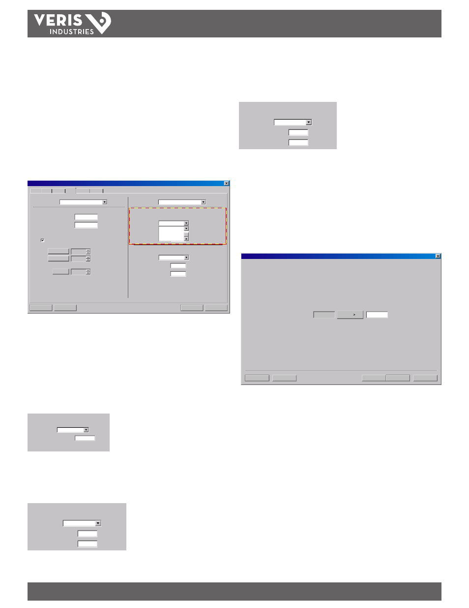
Setting Zero and Calibration
The software utility contains a powerful multi-point calibration routine that can
be used to calibrate the flow meter to a primary measuring standard in a particular
installation. To initialize the three-step calibration routine, click on the Calibration
button located on the top of the Data Screen. The display shown in Figure 5.8 will
appear.
Next>
Cancel File Open... File Save... Calibration (Page 1 of 3) - Zero Flow Set -- -0.88 -0.43 Current Delta T: 1. Make sure flow is at zero. 2. Wait for flow to stabilize. 3. Press . Figure 5.8 - Calibration Page 1 of 3 The first screen (Page 1 of 3) , establishes a baseline zero flow rate measurement for Because every flow meter installation is slightly different and sound waves can To zero the flow meter: 1) Establish zero flow in the pipe (ensure that the pipe is full of fluid, turn off 2) Click the Set button. 3) Click the Next button when prompted, then click the Finish button on the The zeroing process is essential in systems using the FST1, FST2, and FST3
the instrument.
travel in slightly different ways through these various installations, it is important to
remove the zero offset at zero flow to maintain the meters accuracy. A provision is
made using this entry to establish “Zero” flow and eliminate the offset.
all pumps, and close a dead-heading valve). Wait until the delta-time interval
shown in “Current Delta T” is stable (and typically very close to zero).
calibration screen.
transducer sets to ensure the best accuracy.