Caution, Installation guide, Part 1 - monitor installation – Veris Industries FSRxxxx SERIES Install User Manual
Page 7: Transducer connections, Hazard of improper or unsafe operation, Rc us, Pr oduct se rv ice
FSRxxxx SERIES
Z205739-0D
PAGE 7
©2013 Veris Industries USA 800.354.8556 or +1.503.598.4564 / [email protected]
05131
Alta Labs, Enercept, Enspector, Hawkeye, Trustat, Aerospond, Veris, and the Veris ‘V’ logo are trademarks or registered trademarks of Veris Industries, L.L.C. in the USA and/or other countries.
TM
INSTALLATION GUIDE
PART 1 - MONITOR INSTALLATION
After unpacking, save the shipping carton and packing materials in case the
instrument is stored or re-shipped. Inspect the equipment and carton for damage. If
there is evidence of shipping damage, notify the carrier immediately.
Mount the enclosure in an area that is convenient for servicing, calibration, and
observation of the LCD readout.
1. Locate the monitor within the length of transducer cables supplied. If this is
not possible, it is recommended that the cable be exchanged for one that is of
proper length. If additional cable is added, utilize RG59 75 Ω coaxial cable and
BNC connections. Transducer cables that are up to 990 feet (300 meters) can be
accommodated.
2. Mount the monitor in a location:
• Where little vibration exists.
• That is protected from corrosive fluids.
• That is within the monitor’s ambient temperature limits -40 to +185°F
(-40 to +85°C).
• That is out of direct sunlight. Direct sunlight may increase monitor
temperature to above the maximum limit.
3. Mounting - Refer to Figure 1.2 for enclosure and mounting dimension details.
Ensure that enough room is available to allow for door swing, maintenance and
conduit entrances. Secure the enclosure to a flat surface with two appropriate
fasteners.
6.0”
(153 mm)
4.1”
(105 mm)
4.3”
(110 mm)
2.1”
(53 mm)
6.4”
(163 mm)
1.4”
(35 mm)
0.75”
(19 mm)
2x 0.5”
(13 mm)
Figure 1.2 - FSR Dimensions
4. Conduit Holes - Conduit holes should be used where cables enter the enclosure.
Holes not used for cable entry should be sealed with plugs.
Note: Use NEMA 4 [IP-65] rated fittings/plugs to maintain the watertight integrity of the
enclosure. Generally, the right conduit hole (viewed from front) is used for power, the left conduit
hole for transducer connections, and the center hole is utilized for I/O wiring.
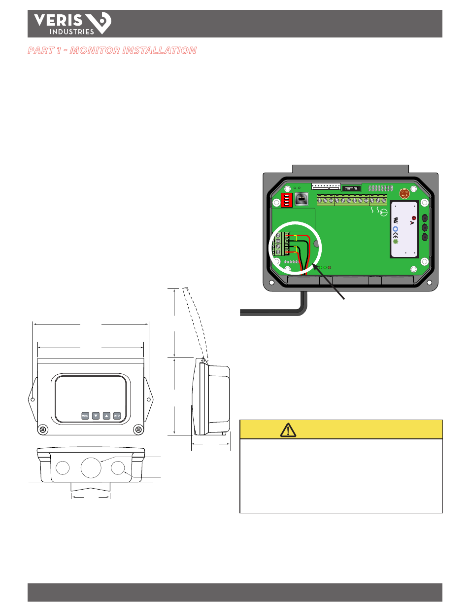
Transducer Connections
To access terminal strips for wiring, loosen the two screws in the enclosure door and
open.
Guide the transducer terminations through the monitor conduit hole located in the
bottom-left of the enclosure. Secure the transducer cable with the supplied conduit
nut (if flexible conduit was ordered with the transducer).
The terminals within the unit are of a screw-down barrier terminal type. Connect
the appropriate wires at the corresponding screw terminals in the monitor. Observe
upstream and downstream (+/–) orientation. See Figure 1.3.
Downstream
Upstream
+
+
-
-
M
odbus
TFX Rx
TFX T
x
Sig
nal Gnd
.
Con
tr
ol 1
Con
tr
ol 2
Frequenc
y O
ut
4-20 mA O
ut
Reset T
otal
M
odbus Gnd
M
odbus B
M
odbus A
95 - 264
VA
C
AC Neutr
al
W
R
C US
1500mA250V
D
VE
372
R
C US
E167432
$
TUV
PR
ODUCT SE
RV
ICE
RoHS
AC IN
: 100-240V
AC
,50/60Hz
DC
OUT :
+15V
/ 0.3A
PWC-15E
0.15A
R2807
www
.astrodyne.com
-Vo
+Vo
ACL
ACN
strodyne
1
2
3
4
O
N
To Transducers
Downstream
Upstream
+
+
-
-
Figure 1.3 - Transducer Connections.
Note: Wire colors may vary!
(+) connection with be either red or blue;
(–) connection will be either black or clear.
Note: The transducer cable carries low level, high frequency signals. Do not add length to the cable
supplied with the transducers. If additional cable is required, contact the manufacturer to arrange
an exchange for a transducer with the appropriate length of cable. Cables to 990 feet (300 meters)
are available. If adding cable, ensure that it is RG59 75 Ω compatible and uses BNC terminations.
Connect power to the screw terminal block in the monitor. See Figure 1.4 and Figure
1.5. Utilize the conduit hole on the right side of the enclosure for this purpose. Use
wiring practices that conform to local and national codes (e.g., The National Electrical
Code® Handbook in the U.S.).
CAUTION
• HAZARD OF IMPROPER OR UNSAFE OPERATION
• This instrument requires clean electrical line power. Do not operate this unit on
circuits with noisy components (e.g., fluorescent lights, relays, compressors, or
variable frequency drives).
• Do not use with high current step-down transformers from high voltage sources.
• Do not run signal wires with line power in the same wiring tray or conduit.
Any other wiring method may be unsafe or cause improper operation of the
instrument.