Veris Industries H970LCA Install User Manual
H970lca, 970lca, Notice
CURRENT MONITORING
Z203252-0E
PAGE 1
©2010 Veris Industries USA 800.354.8556 or +1.503.598.4564 / [email protected]
10101
Alta Labs, Enercept, Enspector, Hawkeye, Trustat, Veris, and the Veris ‘V’ logo are trademarks or registered trademarks of Veris Industries, L.L.C. in the USA and/or other countries.
INSTALLATION GUIDE
TM
Split-Core Low Current 4-20mA & 0-5VDC
DC Current Transducer
Installer’s Specifications
Technology
Open loop Hall effect
Amperage Range
0 to 20/40/80 ADC (slide switch selectable)
Sensor Supply Voltage
15-30VAC/DC for 4-20mA output;
12-30VAC/DC for 0-5VDC output
Supply Current
35mA max.
Isolation
600VAC rms
Temperature Range
-15° to 60°C (5° to 140°F)
Humidity Range
10-90% RH non-condensing
Output
4-20mA and/or 0-5VDC
Accuracy
±3% F.S. combined linearity, hysteresis, and repeatability
The product design provides for basic insulation only.
HAZARD OF ELECTRIC SHOCK, EXPLOSION, OR ARC FLASH
• Follow safe electrical work practices.
See NFPA 70E in the USA, or applicable local codes.
• This equipment must only be installed and serviced by qualified electrical personnel.
• Read, understand and follow the instructions before installing this product.
• Turn off all power supplying equipment before working on or inside the equipment.
• Use a properly rated voltage sensing device to confirm power is off.
DO NOT DEPEND ON THIS PRODUCT FOR VOLTAGE INDICATION
• Only install this product on insulated conductors.
Failure to follow these instructions will result in death or serious injury.
DANGER
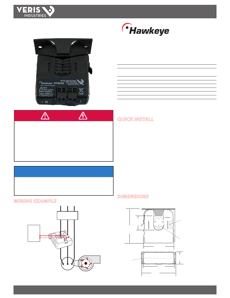
Wiring ExamplE
H970LCA
TM
970LCA
DimEnsions
NOTICE
• This product is not intended for life or safety applications.
• Do not install this product in hazardous or classified locations.
• The installer is responsible for conformance to all applicable codes.
• Mount this product inside a suitable fire and electrical enclosure.
quick install
Disconnect and lock out power to the conductor to be monitored.
1.
Choose a location for the sensor. The monitored conductor must pass through the
2.
iris, and the sensor must be at least 1/2” from any uninsulated conductors.
Install the adjustable mounting bracket to the back of the enclosure using the
3.
included screws.
Connect supply voltage wires to the terminals marked Power (+) and Gnd (-).
4.
Wire the output (mA or VDC) connections between the sensor and the controller.
5.
Snap the sensor over the conductor to be monitored and clip the assembly to the
6.
mounting bracket.
Set the field-selectable switch to the desired amperage level (see page 2).
7.
Fan or Pump
CONTROLLER
4-20mA DC
Analog
Input
MOTOR
CONTACTOR
Removable Mounting Bracket
Self-gripping
Iris
1.0”
(25 mm)
0.8”
(21 mm)
1.1”
(26 mm)
3.1”
(79 mm)
2.8”
(70 mm)
Ø = 0.3”
(8 mm)
1.4”
(36 mm)
2.5”
(64 mm)
3.0”
(76 mm)
Bracket can be mounted
on either side for added
installation flexibility.
Use DIN Rail
Mounting clip
(Veris part
number AH01) to
mount on stan-
dard DIN rail.