Installation guide – Veris Industries FSRxxxx SERIES Install User Manual
Page 48
FSRxxxx SERIES
Z205739-0D
PAGE 48
©2013 Veris Industries USA 800.354.8556 or +1.503.598.4564 / [email protected]
05131
Alta Labs, Enercept, Enspector, Hawkeye, Trustat, Aerospond, Veris, and the Veris ‘V’ logo are trademarks or registered trademarks of Veris Industries, L.L.C. in the USA and/or other countries.
TM
INSTALLATION GUIDE
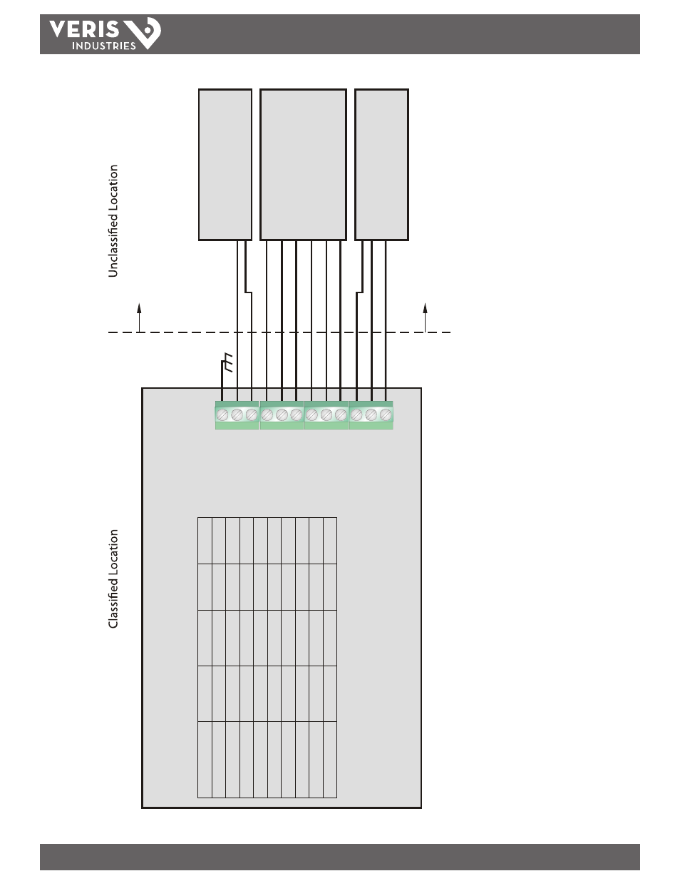
Information shown on this drawing is provided to indicate wiring requirements to comply with the National Electrical Code® (NEC) Article 500, and the Canadian Electric Code (CEC) Part I and Part II.
CONTROL DRAWING,
CLASS I DIV 2 INSTALLATION; DC POWERED
NAME:
Earth Gnd.
10 - 28 Vdc In
Control 2 Out
Freq. Out
Control 1 Out
Signal Gnd.
Power Gnd.
4 - 20 mA Out
Reset
Total
In
Modbus Gnd.
Modbus B
Modbus
A
BY OTHERS
BY OTHERS
FSR1xxxx FLOW METER
Inputs
DC Power
Vmax
28 Vdc
Imax
350 mA
Ci
40 uF
Li
22 uH
Tot
al Reset
28 Vdc
25 mA
0.0 uF
0.0 uH
Outputs
Frequency
Vo
c
28 Vdc
Isc
2.8 mA
Ca
3.3 uF
La
100 mH
Tot
al Pulse
28 Vdc
2.8 mA
3.3 uF
100 mH
4-20 mA
28 Vdc
22 mA
3.3 uF
100 mH
CLASS 2 POWER SUPPLY
Modbus Interface must meet wiring requirements
to comply with NEC Article 500
and the CEC Sections 18 and 18J.
{
Control 2
28 Vdc
2.8 mA
3.3 uF
100 mH
Control 1
28 Vdc
2.8 mA
3.3 uF
100 mH
ASSOCIATED APPARATUS
OTHER DEVICE
Fig
ur
e A
-6
.2 - C
on
tro
l D
ra
wi
ng (
Cla
ss 1
, D
iv I
I D
C)