Garmin G1000 Piper PA32 User Manual
Page 161
GPS NAVIGATION
190-00692-00 Rev. B
5-27
190-00692-00 Rev. B
Garmin G1000 Pilot’s Guide for Piper PA32
N
AVIGATION
S
TATUS
B
OX
Table 5-19 GPS Navigation Status Box
The Navigation Status Box (Figure 5-19) is displayed in the top center of the MFD and PFD. The MFD
contains four user-configurable fields which can display the information listed below. Instructions on
changing a data field are given in the System Overview Section.
• Bearing to next waypoint (BRG)
• Distance to next waypoint (DIS)
• Desired track to next waypoint (DTK)
• Enroute safe altitude (ESA)
• Estimated Time of Arrival (ETA)
• Estimated Time Enroute (ETE)
• Ground Speed (GS)
• Maximum Safe Altitude (MSA)
• True Airspeed (TAS)
• Track angle error (TKE)
• Track angle (TRK)
• Vertical speed required (VSR)
• Cross track error (XTK)
M
EASURING
B
EARING
AND
D
ISTANCE
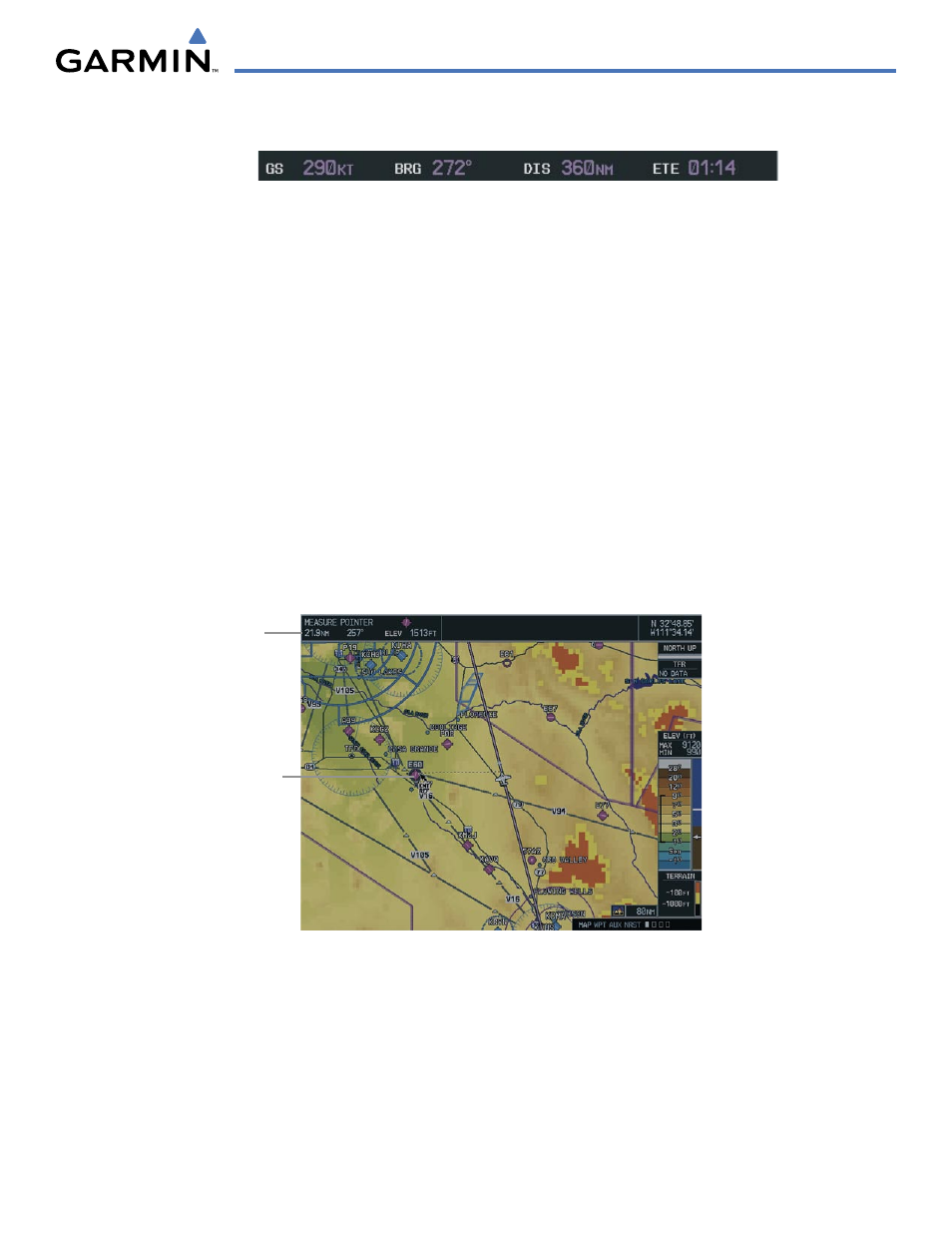
Measure Pointer
Figure 5-20 Measuring Bearing and Distance on the MFD Navigation Map
Callout Items
The ‘Measure Bearing/Distance’ menu option provides a quick and easy method for determining the bearing
and distance between any two points on the Navigation Map.
Pressing the ENT Key at the location selected
with Measure Pointer allows bearing and distance from the newly selected reference to be acquired.