2 connecting a control surface, 3 connecting a video router – NewTek TriCaster 2 Elite (3 RU) User Manual
Page 37
P a g e | 19
3.5.2
CONNECTING A CONTROL SURFACE
Please refer to Section 22.1 for a discussion of connecting and configuring control surfaces.
3.5.3
CONNECTING A VIDEO ROUTER
With the appropriate software installed, your system can control and access output from router models
supporting the popular Grass Valley
®
Native Protocol, as well as Black Magic Design
®
Video Hub routers.
The implementation offers a number of configuration options; a basic setup would be as follows:
•
Connect the router to the system by Ethernet cable, and then connect one (or more) of the router’s
video outputs to SDI inputs with matching numbers, using suitable video cables.
(For example, by default router output number 3 would be connected to
Input 3
for control
communication between the devices to be properly linked.)
•
Click the
Shutdown
icon on the
Home page
(Launch Screen), and click the
Administrator Mode
at right.
•
In the
Administrator Mode
panel, click
Exit to Windows.
•
Navigate to the appropriate folder below:
o
C:\ProgramData\NewTek\TriCaster\Configuration
•
And open the file named
router_setup.xml
by double-clicking it (it will launch in
Notepad
).
This file is where you add the routers you wish to connect. Each router is identified by an entry you insert
between the starting and closing “config” tags, as explained in the file comments.
A typical entry might be as follows:
•
Save the file after editing, and re-launch the system.
Note: The system communicates with routers using individual IP address and port numbers, allowing multiple
routers to be connected simultaneously. File comments explain how you can bypass the default 1:1 mapping
of router outputs to inputs when required, or prevent accidental changes to inputs that are displayed on
Program output, along with other extended configuration options. If you assign names to router inputs or
outputs in this file, make sure the names for each are unique.
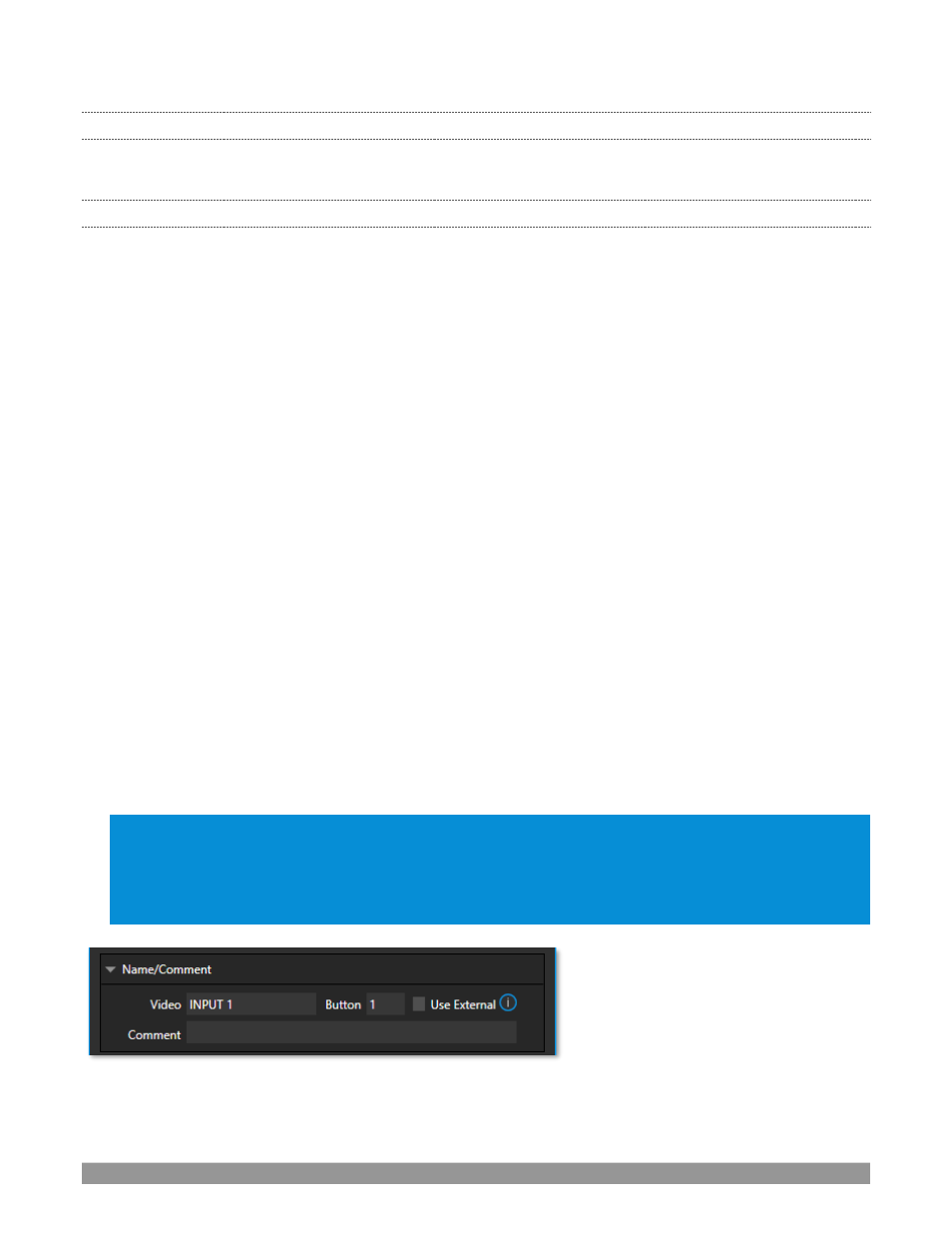
Some routers allow each router input to
be provided with a unique name. In
such a case, the NewTek system may be
able to access that name and use it for
Switcher
buttons as appropriate.
FIGURE 13