NewTek TriCaster 2 Elite (3 RU) User Manual
Page 118
P a g e | 100
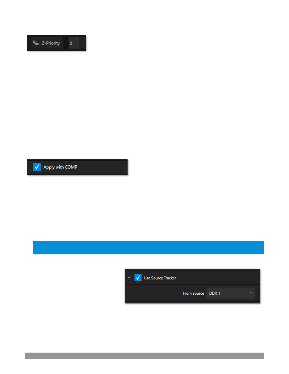
FIGURE 112
The
Priority
setting in
DSK
and
KEY
layer
Positioning
panels allows you to revise the default layer order on a
selective basis. This feature was specially implemented to provide additional flexibility for use with the
Comps
feature.
For example, imagine an
M/E
set up with 4
KEY
s supplying a quad-box setup for four remote interviewees
over a background supplied by the
M/E
. You might want to use
Comps
to zoom the top-left input up to fill
the screen while the moderator chats with that person. Normally,
KEY
s 1-3 would always appear
behind
KEY
4
–
not what you want at all. The
Priority
feature lets you move any KEY to the front (and the setting is stored
in your
Comps
).
The range of
Priority
settings runs from -10 to +10; the default is 0. A layer with a higher index is shown in
front of those with lower indices. When two layers have the same layer priority, they are rendered in their
natural (
DSK/KEY
layer) order.
A
PPLY WITH
C
OMP
FIGURE 113
We will discuss the powerful
Comp
system a bit later (Section 9.9), but
we’ll mention it in passing here to
highlight the
Apply with Comp
switch provided in the
Position
control group. At the lowest level,
Comps
can
be thought of as presets that store complete
Switcher
or
M/E
setups.
By default, the settings stored in a
Comp
include the
Position
,
Crop
and visibility state for each
DSK
or
KEY
layer. Disable the
Apply with Comp
feature if you want to exclude a given DSK/KEY channel from
Comp
control, handling it manually instead.
Hint: You might find this useful, for example,
to ensure that a station ID ‘bug’ shown over output is not
accidentally removed by application of a Comp.
U
SE
S
OURCE
T
RACKER
We discussed the video
Tracker
back in
Section 8.1.4). The
Use Source Tracker
feature lets you assign motion data output
from the
Tracker
for any video source to
modify the position of the current
DSK
or
KEY
layer by selecting it in this menu.
Position
settings enabled above in the
DSK/KEY
tab continue in force but will be applied relative to
Tracker
output. (For example,
X
and
Y Position
settings entered in the upper part of the panel result in an offset from the co-ordinates supplied by the
Tracker
.)
FIGURE 114