Ricoh PJ WU6181N 6200-Lumen WUXGA LCD Projector (No Lens) User Manual
Page 258

243
10. Appendix
❺
Pin assignments and signal names of main connectors
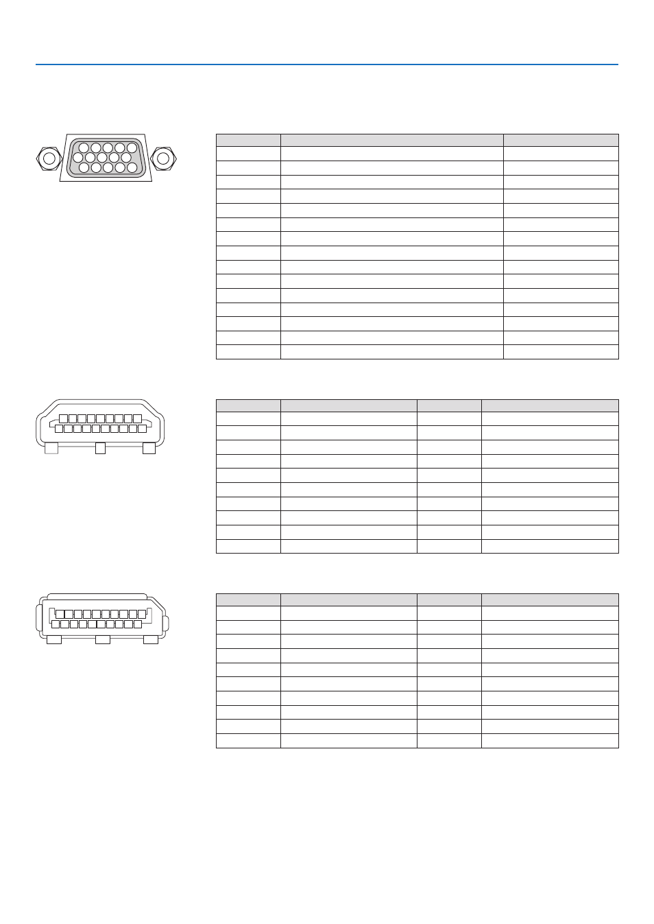
COMPUTER IN/ Component Input Connector (Mini D-Sub 15 Pin)
Connection and signal level of each pin
5
1
4
2 3
10
11 12 13 14 15
6
9
7 8
Signal Level
Video signal : 0.7Vp-p (Analog)
Sync signal : TTL level
Pin No.
RGB Signal (Analog)
YCbCr Signal
1
Red
Cr
2
Green or Sync on Green
Y
3
Blue
Cb
4
Ground
5
Ground
6
Red Ground
Cr Ground
7
Green Ground
Y Ground
8
Blue Ground
Cb Ground
9
No Connection
10
Sync Signal Ground
11
No Connection
12
Bi-directional DATA (SDA)
13
Horizontal Sync or Composite Sync
14
Vertical Sync
15
Data Clock
HDMI 1 IN/HDMI 2 IN Connector (Type A)
1 3 5 7 9 11 13 15 17 19
2 4 6 8 10 12 14 16 18
Pin No.
Signal
Pin No.
Signal
1
TMDS Data 2+
11
TMDS Clock Shield
2
TMDS Data 2 Shield
12
TMDS Clock−
3
TMDS Data 2−
13
CEC
4
TMDS Data 1+
14
Disconnection
5
TMDS Data 1 Shield
15
SCL
6
TMDS Data 1−
16
SDA
7
TMDS Data 0+
17
DDC/CEC grounding
8
TMDS Data 0 Shield
18
+5 V power supply
9
TMDS Data 0−
19
Hot plug detection
10
TMDS Clock +
DisplayPort IN Connector
1 3 5 7 9 11 13 15 17 19
2 4 6 8 10 12 14 16 18 20
Pin No.
Signal
Pin No.
Signal
1
Main link lane 3−
11
Grounding 0
2
Grounding 3
12
Main link lane 0+
3
Main link lane 3+
13
Configuration 1
4
Main link lane 2−
14
Configuration 2
5
Grounding 2
15
Supplementary channel +
6
Main link lane 2+
16
Grounding 4
7
Main link lane 1−
17
Supplementary channel −
8
Grounding 1
18
Hot plug detection
9
Main link lane 1+
19
Return
10
Main link lane 0−
20
+3.3 V power supply
