2) brake signal (/bk) setting, 3) brake signal (/bk) allocation – Yaskawa Σ-V Series AC Servo Drives Rotational Motor Analog Voltage Reference User Manual
Page 91
5.2 Basic Functions Settings
5-11
5
Op
er
at
io
n
(2) Brake Signal (/BK) Setting
This output signal controls the brake. The output signal must be allocated with Pn50F. Refer to
(3) Brake Sig-
nal (/BK) Allocation
for allocation.
The /BK signal turns OFF (applies the brake) when an alarm is detected or the /S-ON signal is turned OFF.
The brake OFF timing can be adjusted with Pn506.
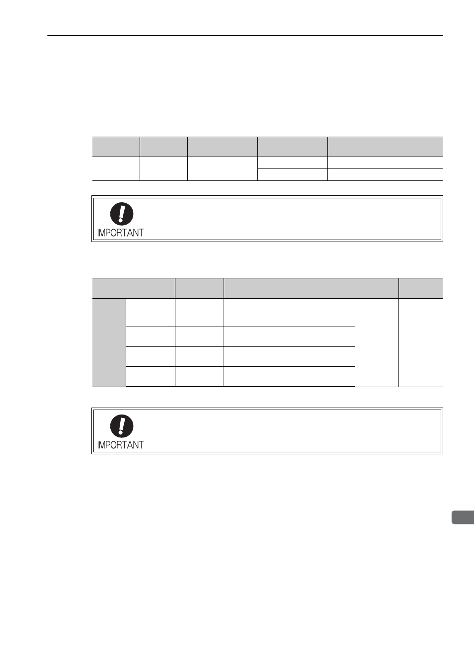
(3) Brake Signal (/BK) Allocation
The brake signal (/BK) is not allocated at shipment. Use parameter Pn50F.2 to allocate the /BK signal.
Type
Name
Connector
Pin Number
Setting
Meaning
Output
/BK
Must be allocated
ON (closed)
Releases the brake.
OFF (open)
Applies the brake.
The /BK signal is still ON during overtravel and the brake is still released.
Parameter
Connector
Pin Number
Meaning
When
Enabled
Classifica-
tion
Pn50F
n. 0
[Factory
setting]
–
The /BK signal is not used.
After restart
Setup
n. 1
CN1-7
The /BK signal is output from output termi-
nal CN1-7.
n. 2
CN1-9
The /BK signal is output from output termi-
nal CN1-9.
n. 3
CN1-10
The /BK signal is output from output termi-
nal CN1-10.
When multiple signals are allocated to the same output terminal, the signals are output
with OR logic. For the /BK signal, do not use the output terminal that is already being
used for another signal.