9 absolute encoders, 1 connecting the absolute encoder, Analog – Yaskawa Σ-V Series AC Servo Drives Rotational Motor Analog Voltage Reference User Manual
Page 139
5.9 Absolute Encoders
5-59
5
Op
er
at
io
n
5.9
Absolute Encoders
If using an absolute encoder, a system to detect the absolute position can be designed for use with the host
controller. As a result, an operation can be performed without a zero point return operation immediately after
the power is turned ON.
A battery case is required to save position data in the absolute encoder.
The battery is attached to the battery case of the encoder cable.
Set Pn002.2 to 0 (factory setting) to use the absolute encoder.
The SEN signal and battery are not required when using the absolute encoder as an incremental encoder.
5.9.1
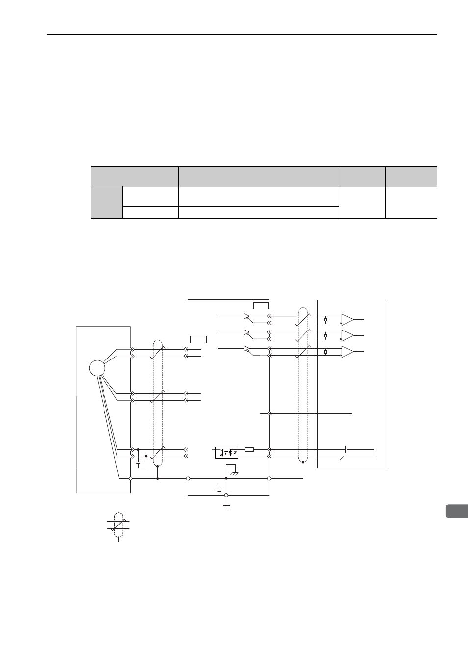
Connecting the Absolute Encoder
The following diagram shows the connection between a servomotor with an absolute encoder, the SERVO-
PACK, and the host controller.
∗1.
: represents shielded twisted-pair wires.
∗2.
When using an absolute encoder, provide power by installing an encoder cable with a JUSP-BA01-E Battery Case or
install a battery on the host controller.
∗3.
If using an absolute encoder, allocate the SEN signal to one of the seven input signals.
Parameter
Meaning
When
Enabled
Classification
Pn002
n. 0
[Factory setting]
Uses the absolute encoder as an absolute encoder.
After restart
Setup
n. 1
Uses the absolute encoder as an incremental encoder.
/PCO
ENC
3
4
14
3.3 k
Ω
+24 VIN
/SEN
∗
3
CN2
19
20
21
22
23
24
CN1
SG
13
PAO
/PAO
PBO
/PBO
PCO
∗
1
∗
1
0 V
+24 V
5
6
1
2
PG5 V
PG0 V
PS
/PS
BAT (+)
BAT (-)
R
R
R
∗
2
∗
2
0 V
Phase A
Phase B
Phase C
Connector
shell
Connector
shell
SN75ALS174
output line driver or
the equivalent
Phase A
Phase B
Phase C
Applicable line receiver: SN75ALS175
or MC3486 manufactured by Texas
Instruments or the equivalent
Terminating resistance R: 220 to 470
Ω
Absolute encoder
SERVOPACK
Host controller
(Shell)
Battery
Analog