3 monitoring operation during adjustment, 1) connecting the measurement instrument, 2) monitor signal – Yaskawa Σ-V Series AC Servo Drives Rotational Motor Analog Voltage Reference User Manual
Page 156: Analog, Analog voltage reference
6.1 Type of Adjustments and Basic Adjustment Procedure
6-5
6
Adjustments
6.1.3
Monitoring Operation during Adjustment
While adjusting the servo gain, always monitor the operating status of the machine and the signal waveform.
Connect a measurement instrument, such as a memory recorder, to the SERVOPACK to monitor the signal
waveform.
The settings and parameters that are related to monitoring the analog signal are described in the following sec-
tions.
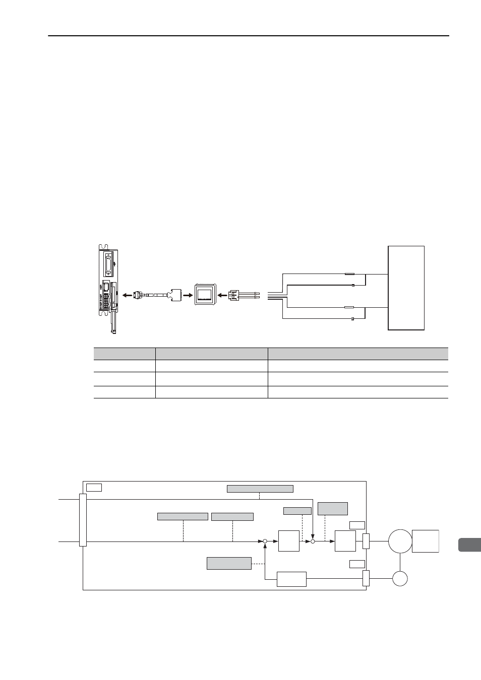
(1) Connecting the Measurement Instrument
Use the external monitor connector (CN5) on the SERVOPACK to connect the measurement instrument. The
devices and cables that are required for connection are listed below.
• Analog monitor unit (model: JUSP-PC001-E)
• Analog monitor unit connection cable (model: JZSP-CF1S05-A3-E)
• Analog monitor cable (model: JZSP-CA01-E)
Connection examples are shown below.
∗
Measuring instrument is not included.
(2) Monitor Signal
The shaded parts in the following diagram indicate analog output signals that can be monitored.
Analog Voltage Reference
Probe GND
Measuring probe
Measuring probe
Probe GND
Measuring
instrument*
White
Red
Black
Black
Connection
cable for analog
monitor unit
Cable for
analog monitor
Analog
monitor
unit
Analog
Line Color
Signal Name
Factory Setting
White
Analog monitor 1
Torque reference: 1 V/100% rated torque
Red
Analog monitor 2
Motor speed: 1 V/1000 min
-1
Black (2 lines)
GND
Analog monitor GND: 0 V
(U/V/W)
-
+
+
+
T-REF
V-REF
M
ENC
CN2
CN4
CN1
SERVOPACK
Speed feedforward
Motor rotational
speed
Speed reference
Active gain
Torque
reference
Torque feedforward
Load
Speed
conversion
Speed
loop
Current
loop
Analog