Yaskawa Σ-V Series AC Servo Drives Rotational Motor Analog Voltage Reference User Manual
Page 70
4.3 Trial Operation for Servomotor without Load from Host Reference
4-5
4
Tria
l Ope
ra
tio
n
4.3.1
Inspecting Connection and Status of Input Signals
Check the items in step 1 before trial operation of the servomotor under speed control (Analog voltage refer-
ence) and position control (Pulse train reference) from the host controller.
Check the connection and status of input signals using the following procedure.
Step
Operation
Reference
1
Connect the necessary input signals to the I/O signal connector (CN1) under the following con-
ditions.
• It must be possible to input servo ON signal (/S-ON).
• The forward run prohibited (P-OT) and reverse run prohibited (N-OT) input signals must be
ON (L level) (i.e., the servomotor must be able to run in forward and reverse).
Settings: CN1-17 and CN1-18 must be ON (low) or Pn50A.3 and Pn50B.0 must be set to 8 to
disable the forward and reverse run prohibited function.
Note: Return the settings to the previous ones after completing trial operation.
• Make sure that there is no reference input.
Note: If Pn002.2 is set to 1, the absolute encoder can temporarily be used as an incremental
encoder, which makes it possible to perform trial operation of the servomotor without
Fn008 and SEN signal settings.
Refer to the following connec-
tion diagrams.
3.2.2 Example of I/O Signal
Connections in Speed Control
(Analog Voltage Reference)
3.2.3 Example of I/O Signal
Connections in Position Con-
trol (Pulse Train Reference)
3.2.4 Example of I/O Signal
Connections in Torque Control
(Analog Voltage Reference)
5.9 Absolute Encoders
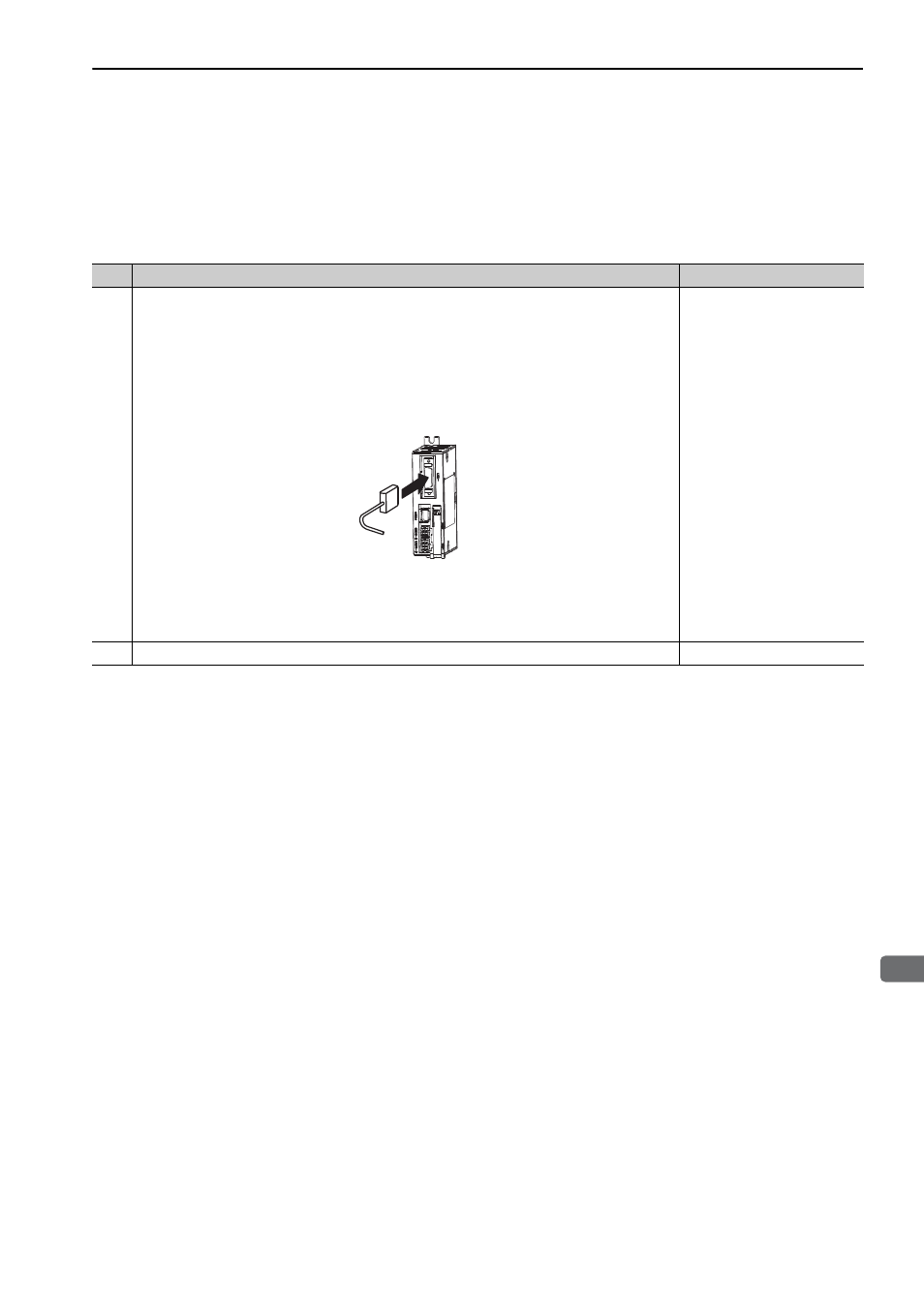
2
Connect the connector of the host controller to the I/O signal connector (CN1).
–
CN1