2 connection to omron’s position control unit, Analog – Yaskawa Σ-V Series AC Servo Drives Rotational Motor Analog Voltage Reference User Manual
Page 285
10.1 Connection to Host Controller
10-3
10
Ap
pend
ix
10.1.2
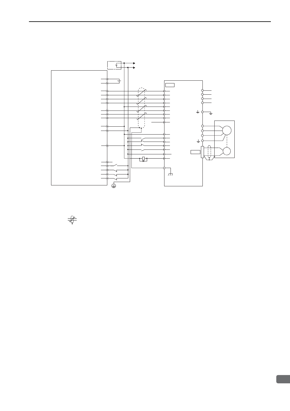
Connection to OMRON’s Position Control Unit
∗1.
The ALM signal is output for about five seconds after the control power is turned ON. Take this into consideration
when designing the power ON sequence. Also, use the ALM signal to actuate the alarm detection relay 1Ry to stop
the main circuit power supply to the SERVOPACK.
∗2.
Set parameter Pn200.0 to "1."
∗3.
Connect the shielded wire to the connector shell.
∗4.
represents twisted-pair wires.
Note 1. Only the signals related to the DC power input
Σ
-V Series SERVOPACK and the OMRON Position Control Unit
are shown in the diagram.
2. Incorrect signal connections will damage the Position Control Unit or SERVOPACK. Wire all connections care-
fully.
3. Open the signal lines not to be used.
4. The above connection diagram shows only X-axis connections. When using other axes, make connections to the
SERVOPACK in the same way.
5. Short-circuit the normally closed (NC) input terminals that are not used at the I/O connector section of the posi-
tion control unit.
6. Make the settings so that the servomotor can be turned ON/OFF by the Servo ON (/S-ON) signal.
Position Control Unit
manufactured by OMRON Corporation
CS1W-NC133 / 233 / 433
Servomotor
SGDV-
EP1A
SERVOPACK
5-V power supply for pulse output
5-V GND for pulse output
24-V power supply for output
24-V GND for output
CCW(+) output
CCW(-) output
CW(+) output
CW(-) output
Origin input signal
Origin input common
Error counter reset output
X-axis CW limit input
X-axis CCW limit input
X-axis immediate stop input
X-axis external interrupt input
X-axis origin proximity input
Connector
shell
Control power supply
Main circuit power supply
I/O power supply
CN2
CN1
A3
A5
A6
A7
A4
2
24
7
C1
L2
L1
C2
23
4
1
6
5
W
V
U
A16
A11
A14
A1
A2
A8
A20
A22
A23
A21
A19
3
/SIGN
CLR
/CLR
PCO
PULS
/PULS
SIGN
/PCO
/COIN
A24
8
11
25
17
18
14
15
+24-V-IN
/S-ON
P-OT
N-OT
/ALM-RST
COM_SG
ALM
1Ry
FG
∗
1
∗
2
∗
3
∗
4
+5 V
Input common
M
ENC
+
-
+24 V
0
24
+24
V
Analog