Analog – Yaskawa Σ-V Series AC Servo Drives Rotational Motor Analog Voltage Reference User Manual
Page 47
3 Wiring and Connection
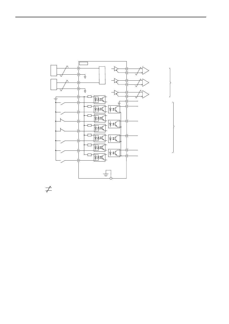
3.2.4 Example of I/O Signal Connections in Torque Control (Analog Voltage Reference)
3-12
3.2.4
Example of I/O Signal Connections in Torque Control (Analog Voltage
Reference)
Connection example in torque control is as shown below.
∗1.
represents twisted-pair wires.
∗2.
If using an absolute encoder, allocate the SEN signal to one of the seven input signals.
∗3.
Enabled by the parameter setting.
∗4.
The 24-VDC power supply is not included. Use a 24-VDC power supply with double insulation or reinforced insula-
tion.
∗5.
Always use line receivers to receive the output signals.
∗
5
∗
5
∗
5
PBO
PCO
/PBO
PAO
/PAO
/PCO
/VLT
SG
ALM
/TGON
/S-RDY
COM SG
4
8
9
10
11
7
13
23
19
20
21
22
24
+24 V
+24 VIN
3.3 k
Ω
/S-ON
/P-CON
P-OT
N-OT
/ALM-RST
/N-CL
14
16
18
17
25
26
/P-CL
12
15
V-REF
SG
A / D
1
2
∗
1
T-REF
SG
3
∗
4
∗
3
FG
CN1
D/A
D/A
∗
2
SERVOPACK
Servo ON
(Servo ON when ON)
Reverse run prohibited
(Prohibited when OFF)
Forward run prohibited
(Prohibited when OFF)
Alarm reset
(Reset when ON)
Reverse external torque limit
(Limit when ON)
Forward external torque limit
(Limit when ON)
P control
(P control when ON)
Torque reference
(Max. input voltage
range: ± 12 V)
External speed limit
(Max. input voltage
range: ± 12 V)
Rotation detection output
(ON when the motor speed
exceeds the settings.)
Servo alarm output
(OFF for an alarm)
Photocoupler output
Max. operating voltage:
30 VDC
Max. output current:
50 mA DC
Speed limit output
*3
(ON when the motor's
running speed is limited.)
Servo ready output
(ON when ready)
Encoder output
pulse phase A
Encoder output
pulse phase B
Encoder output
pulse phase C
Applicable line
receiver:
SN75ALS175 or
MC3486
manufactured by
Texas Instruments or
the equivalent
Connect shield to
connector shell.
Connector
shell
SERVOPACK
Analog