Yaskawa Σ-V Series AC Servo Drives Rotational Motor Analog Voltage Reference User Manual
Page 50
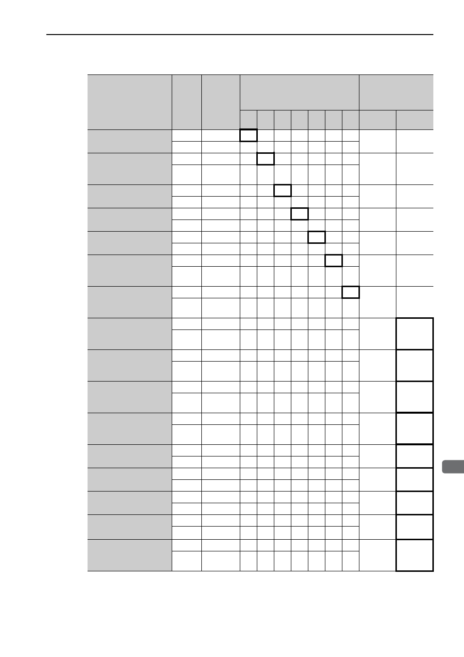
3.3 I/O Signal Allocations
3-15
3
Wi
ring and
C
onne
ctio
n
∗
If using an absolute encoder, allocate the SEN signal to one of the seven input signals.
Input Signal Names
and Parameters
Validity
Level
Input
Signal
CN1 Pin Numbers
Connection Not
Required
(SERVOPACK judges
the connection)
15
16
17
18
25
26
12
Always
ON
Always
OFF
Servo ON
Pn50A.1
L
/S-ON
0
1
2
3
4
5
6
7
8
H
S-ON
9
A
B
C
D
E
F
Proportional Operation
Reference
Pn50A.2
L
/P-CON
0
1
2
3
4
5
6
7
8
H
P-CON
9
A
B
C
D
E
F
Forward Run Prohibited
Pn50A.3
H
P-OT
0
1
2
3
4
5
6
7
8
L
/P-OT
9
A
B
C
D
E
F
Reverse Run Prohibited
Pn50B.0
H
N-OT
0
1
2
3
4
5
6
7
8
L
/N-OT
9
A
B
C
D
E
F
Alarm Reset
Pn50B.1
L
/ARM-RST
0
1
2
3
4
5
6
–
8
H
ARM-RST
9
A
B
C
D
E
F
Forward External
Torque Limit
Pn50B.2
L
/P-CL
0
1
2
3
4
5
6
7
8
H
P-CL
9
A
B
C
D
E
F
Reverse External
Torque Limit
Pn50B.3
L
/N-CL
0
1
2
3
4
5
6
7
8
H
N-CL
9
A
B
C
D
E
F
Switching Servomotor
Rotation Direction
Pn50C.0
L
/SPD-D
0
1
2
3
4
5
6
7
8
H
SPD-D
9
A
B
C
D
E
F
Internal Set Speed
Control
Pn50C.1
L
/SPD-A
0
1
2
3
4
5
6
7
8
H
SPD-A
9
A
B
C
D
E
F
Internal Set Speed
Control
Pn50C.2
L
/SPD-B
0
1
2
3
4
5
6
7
8
H
SPD-B
9
A
B
C
D
E
F
Control Method
Selection
Pn50C.3
L
/C-SEL
0
1
2
3
4
5
6
7
8
H
C-SEL
9
A
B
C
D
E
F
Zero Clamp
Pn50D.0
L
/ZCLAMP
0
1
2
3
4
5
6
7
8
H
ZCLAMP
9
A
B
C
D
E
F
Reference Pulse Inhibit
Pn50D.1
L
/INHIBIT
0
1
2
3
4
5
6
7
8
H
INHIBIT
9
A
B
C
D
E
F
Gain Changeover
Pn50D.2
L
/G-SEL
0
1
2
3
4
5
6
7
8
H
G-SEL
9
A
B
C
D
E
F
SEN Signal
*
Pn515.0
L
/SEN
0
1
2
3
4
5
6
7
8
H
SEN
9
A
B
C
D
E
F
Reference Pulse Input
Multiplication Switching
Pn515.1
L
/PSEL
0
1
2
3
4
5
6
7
8
H
PSEL
9
A
B
C
D
E
F