4) checking input signals – Yaskawa Σ-V Series AC Servo Drives Rotational Motor Analog Voltage Reference User Manual
Page 52
3.3 I/O Signal Allocations
3-17
3
Wi
ring and
C
onne
ctio
n
∗
If the
Key has not been pressed but the
Key has been pressed to select another mode such as the utility func-
tion mode, any changes that have been made to the parameter will be saved in the SERVOPACK.
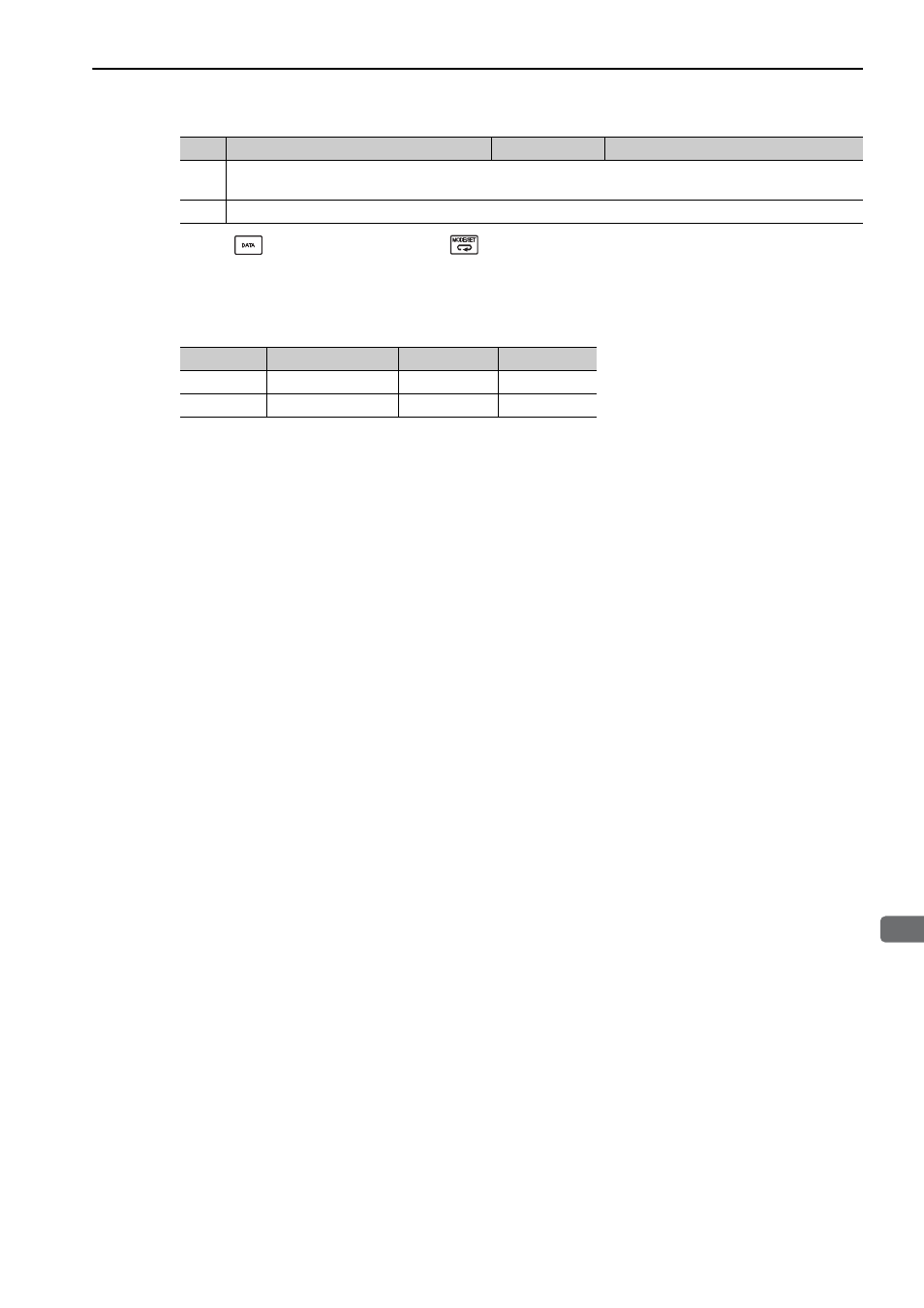
Input signal polarities are as follows when sequence input circuit is connected to a sink circuit. If connected to
a source circuit, polarities are reversed. For details, refer to
3.4.2 Sequence Input Circuit
.
(4) Checking Input Signals
Input signal status can be checked using the input signal monitor (Un005). As for the input signal monitor
(Un005), refer to
8.3 Monitoring Input Signals.
10
Refer to steps 5 to 9 and change the set value of Pn50B from n.6543 to n.6043.
Note: If setting Pn50B.2 to 0, the allocation for /P-CL can be changed from CN1-26 to CN1-15.
11
To enable the change in the setting, restart the SERVOPACK.
Signal
Level
Voltage Level
Contact
ON
Low (L) level
0 V
Close
OFF
High (H) level
24 V
Open
Step
Display after Operation
Keys
Operation