4 examples of connection to host controller, 1 reference input circuit, 1) analog input circuit (analog voltage reference) – Yaskawa Σ-V Series AC Servo Drives Rotational Motor Analog Voltage Reference User Manual
Page 57
3 Wiring and Connection
3.4.1 Reference Input Circuit
3-22
3.4
Examples of Connection to Host Controller
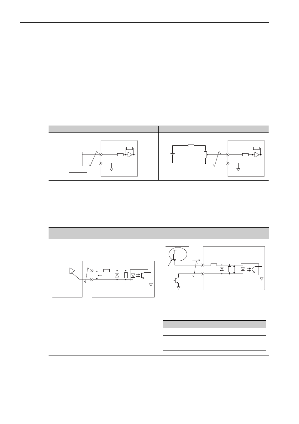
This section shows examples of SERVOPACK I/O signal connection to the host controller.
3.4.1
Reference Input Circuit
(1) Analog Input Circuit (Analog Voltage Reference)
CN1 connector terminals, 1-2 (speed reference input) and 3-4 (torque reference input) are explained below.
Analog signals are either speed or torque reference signals at the impedance below.
• Reference speed input: Approx. 14 k
Ω
• Reference torque input: Approx. 14 k
Ω
The maximum allowable voltages for input signals is ±12 V.
∗
This wiring example is for forward operation.
(2) Position Reference Input Circuit (Pulse Train Reference)
CN1 connector terminals, 1-2 (reference pulse input), 3-4 (reference sign input) and 5-6 (clear input) are
explained below. The output circuits for the reference pulse and position error clear signal from the host con-
troller can be either a line-driver output or open-collector output. The position reference input circuits are
shown below by output type.
Analog Voltage Input Circuit (D/A)
Analog Voltage Input Circuit (Wiring Example)*
Host controller
0 V
SG
SERVOPACK
V-REF or
T-REF
D/A
Approx.14 k
Ω
min.
25HP-10B
2 k
Ω
Approx.14 k
Ω
min.
1.8 k
Ω
(1/2 W) min.
12 V
0 V
SG
SERVOPACK
V-REF or
T-REF
Line-driver Output Circuit
Open-collector Output Circuit
(Power supply not included.)
Before wiring, confirm that the specifications of the host con-
troller satisfy the values shown in the following table.
If these conditions are not satisfied, the SERVOPACK may
malfunction.
2.8 V
≤
(H level)
−
(L level)
≤
3.7 V
Applicable line
driver:
SN75ALS174
manufactured by
Texas Instruments
or the equivalent
If the above formula is not satisfied,
the inputs to the SERVOPACK will be
unstable. Pulses may be missed from
the reference pulse input, reference
inversion may occur for the reference
sign input, and the clear signal may
be OFF for the clear input.
150
Ω
4.7 k
Ω
Host controller
SERVOPACK
SERVOPACK
VF = 1.5 to 1.8 V
Vcc
Tr1
VF
R1
i
Host controller
150
Ω
4.7 k
Ω
Pull-up
Pull-up voltage (Vcc)
Pull-up resistance (R1)
24 V
1.8 to 2.7 k
Ω
12 V or less
820
Ω
to 1.5 k
Ω
5 V or less
180 to 470
Ω