4 monitoring output signals, 1 interpreting output signal display status, 2 output signal display example – Yaskawa Σ-V Series AC Servo Drives Rotational Motor Analog Voltage Reference User Manual
Page 259: Analog
8 Monitor Displays (Un
)
8.4.1 Interpreting Output Signal Display Status
8-6
8.4
Monitoring Output Signals
The status of output signals can be checked with the output signal monitor (Un006). The method of interpret-
ing the display and a display example are shown below.
8.4.1
Interpreting Output Signal Display Status
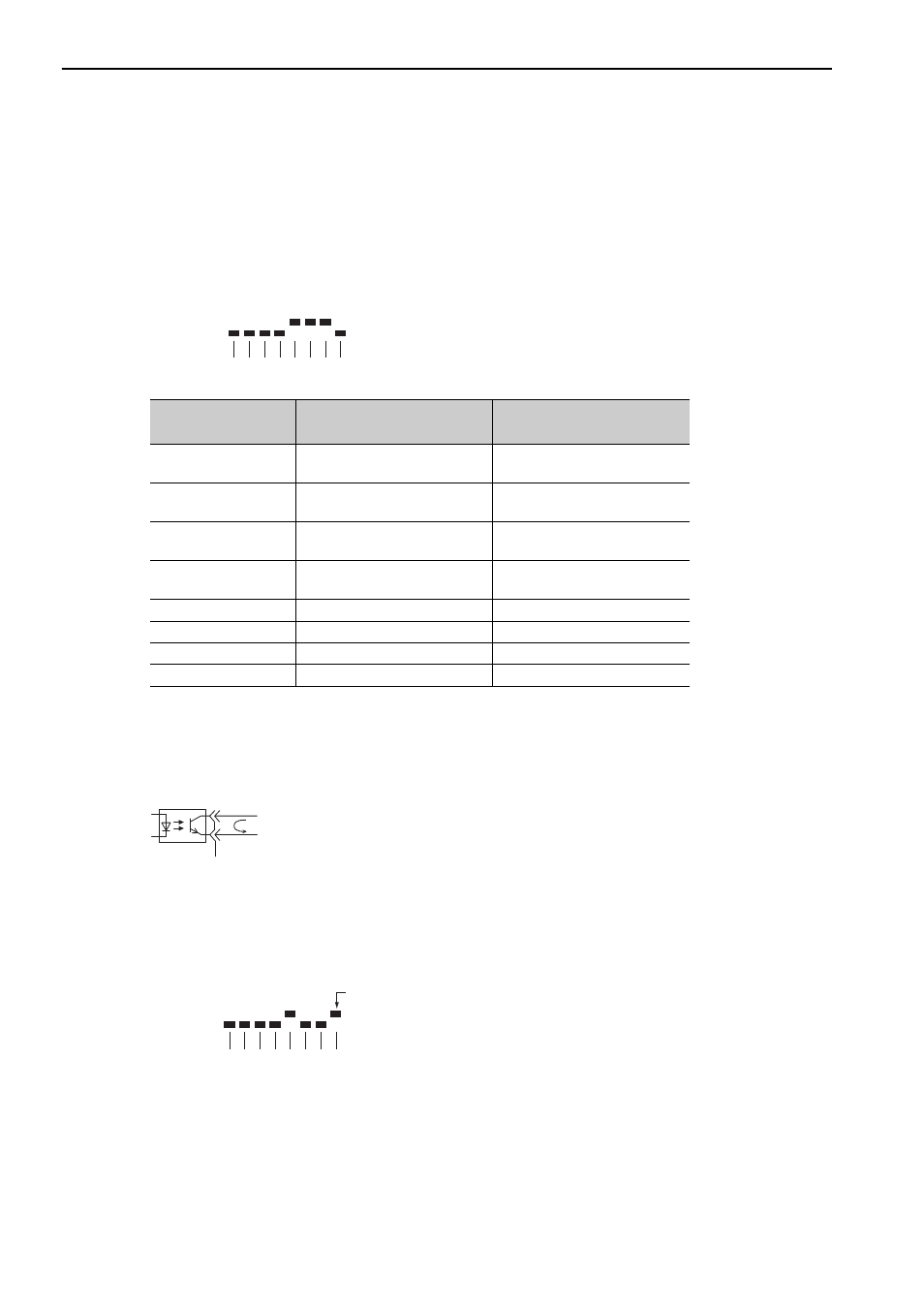
The output signal monitor (Un006) can be read in the following way. The upper level indicates OFF, and the
lower level indicates ON. All undefined digits are shown in the lower level (ON).
Note: Output signals use the following circuit configuration.
• OFF: Transistor OFF
• ON: Transistor ON
Example
8.4.2
Output Signal Display Example
Output signals are displayed as shown below.
• When the ALM signal is OFF
Display LED
Number
Output Terminal Name
Signal Name
(Factory Setting)
1
CN1-8
(cannot be allocated)
ALM
2
CN1-7
(can be allocated)
/COIN or /V-CMP
3
CN1-9
(can be allocated)
/TGON
4
CN1-10
(can be allocated)
/S-RDY
5
−
Reserved
6
−
Reserved
7
−
Reserved
8
−
Reserved
U n 0 0 6 =
8 7 6 5 4 3 2 1 digit
Analog
ON: Transistor ON
Analog
U n 0 0 6 =
8 7 6 5 4 3 2 1 digit
The first digit is
in the upper level.
Analog