3 secondary scrolling status messages – Magnum Energy ME-RTR Router User Manual
Page 70
©
2014 Magnum Energy, Inc.
Page 62
Operation
5.3.3
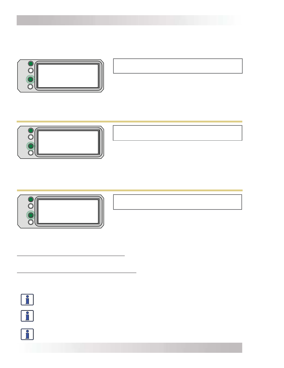
Secondary Scrolling Status Messages
These displays alternate with the inverter’s primary status to indicate other pertinent messages.
Note: Depending on circumstances, the lighting sequence of the LED indicators may vary as there
can be several secondary status messages scrolling at any one time.
FAULT
PWR
CHG
INV
AC In - Disabled
Settings/Info...
AC In – Disabled appears on LCD. PWR (green) LED
is on solid and CHG (green) LED is blinking.
Figure 5-22, AC In – Disabled Mode
•
AC In – Disabled – AC power is present at the inverter’s AC input, but the inverter/charger
is prevented from connecting to any incoming AC because the AC In – Disabled setting is selected
from the CTRL: 01 AC In Control menu.
• Gen
Warm-up
– The ME-AGS-N has commanded a generator to run, but the inverter will not
connect to the generator’s AC output until the generator warm-up time is complete.
Note: Requires the optional ME-AGS-N Auto Gen Start module to be connected.
FAULT
PWR
CHG
INV
Max Charge Time
Settings/Info...
FAULT
PWR
CHG
INV
Gen Warm-up
Settings/Info...
Max Charge Time appears on LCD. PWR (green) LED
is on solid and CHG (green) LED is blinking.
Gen Warm-up appears on LCD. PWR (green) LED is
on solid and CHG (green) LED is blinking.
Figure 5-24, Max Charge Time Mode
Figure 5-23, Gen Warm-up Mode
•
Max Charge Time – This display indicates the Max Charge Time safety feature was enabled
because the charge time was longer than the Max Charge: Time setting.
If SETUP/03C Battery Type: CC/CV is selected: The charger was forced to transition to the Silent
charge stage because the charger had been in Constant Current and Constant Voltage charge
modes longer than the Max Charge: Time setting [under the Chg Done Time (or Amps) selection].
If SETUP/03C Battery Type: CC/CV is not selected: The charger was forced to transition to the
fi nal charge stage (Float, Silent, or Full Charge) as set under the SETUP button’s 03F Final Charge
Stage. This safety feature occurred because the charger had been in Bulk, Absorption, or EQ charge
modes longer than the Max Charge: Time setting.
Info: The Max Charge Time safety feature uses the time accumulated under the METER:
03A Charge Time display to determine the total charge time.
Info: The Max Charge: Time display can be reset by either reconnecting AC to the
inverter (causing the charge status to go to “Charging”), initiating another charge cycle
(Bulk, EQ, or Constant Current), or turning the Max Charge Time feature off.
Info: The timer for the Max Charge: Time menu runs when the battery voltage is
greater than 0.2 volts above the fl oat voltage setting.