6 mounting the router on a wall, 7 connecting the communication cables, Ab c d – Magnum Energy ME-RTR Router User Manual
Page 16
©
2014 Magnum Energy, Inc.
Page 8
Installation
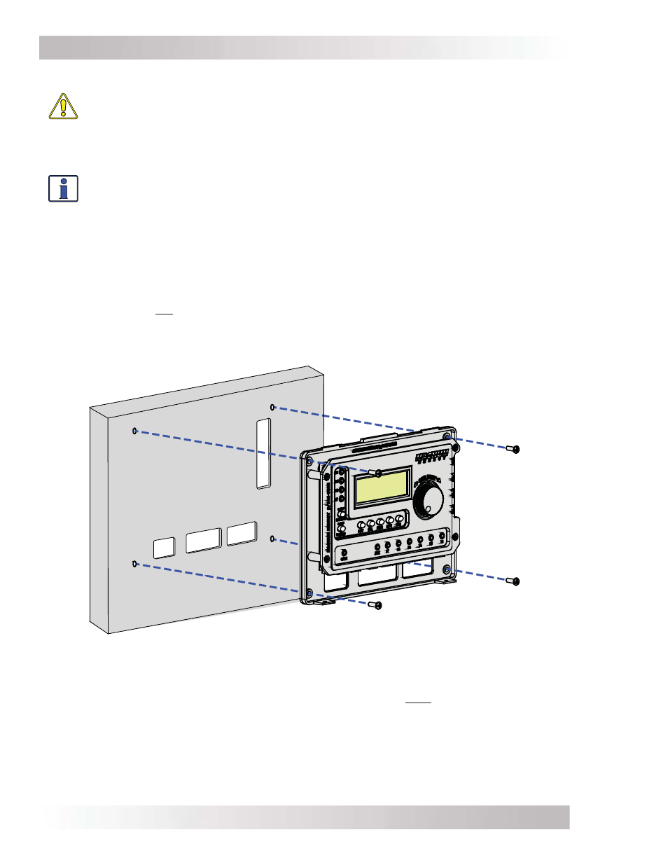
Cutout sections A-D to
accommodate routing
wires behind wall.
A
B
C
D
Figure 2-9, Mounting the Router to a Wall
2.6
Mounting the Router on a Wall
CAUTION: The router must be located close to the inverter/chargers (within six feet).
The router is designed to exchange data from the master inverter with one or multiple
slave inverters. The high speed communication data between the stack ports on the
router and the inverter ensure the slave inverters are synchronized to the master
inverter. To ensure the communications is not impacted, DO NOT exceed the 6-foot
stack cable distance between the router and each connected inverter.
Info: If a more distant monitoring location is required (more than six feet), a ME-RC50
or ME-ARC50 remote control may be connected and acts as a remote on/off switch to
assist in monitoring the system. See Section 9.0 for more information.
To mount the router on the surface of a wall:
1. Select an appropriate location to install the router (see Figures 2-2 & 2-3 for the router’s
dimensions).
2. Remove the router’s front cover, and then use the router bezel as a template to mark the
screw holes and the sections of the wall (or mounting surface) to remove to accommodate the
routing of the communication wires (Sections A-D on Figure 2-9).
Note: If you are not routing the communication wires thru the wall, there is no need to cut
sections from the wall.
3. Once the screw holes have been drilled and the optional wall sections are removed, mount the
router bezel to the wall using the 4 screws that are provided.
2.7 Connecting the Communication Cables
The stack and remote communication cables are used to connect each inverter/charger directly
to the router. A network cable is used to connect accessories to the router.
Each paralleled inverter/charger requires a high speed parallel stack cable connected to a stack
port on the router—marked MA (Master), SL1 (Slave 1), SL2 (Slave 2), and SL3 (Slave 3)—see
Figure 2-1. One inverter/charger will always be designated the “Master”, and subsequently any
other connected inverter/chargers are designated as “Slaves”. You can stack up to four MS-PAE
or MS-PE Series inverter/chargers using one router. It is recommended that you set up the Master
inverter as the fi rst unit on the left, and Slave 1 as the second unit, etc.