5 communications cable routing – Magnum Energy ME-RTR Router User Manual
Page 15
Page 7
©
2014 Magnum Energy, Inc.
Installation
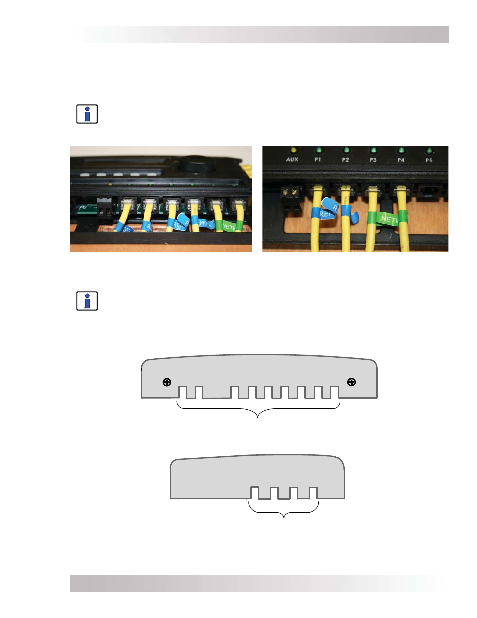
BOTTOM VIEW – ROUTER COVER
Remote and network cable cutouts (x9)
RIGHT SIDE VIEW – ROUTER COVER
Stack cable cutouts (x4)
Figure 2-8, Router Front Cover’s Cable Connection Cutouts
Info: If the cables are installed on the surface, the router’s front cover has cutout
sections to accommodate the cables (see Figure 2-8). These cutout sections are made
thinner to allow them to be easily broken or cut. Only remove those cutout sections
needed for the number of cable connections you are installing.
Figure 2-6, Concealed Mounted
Remote/Network Cables
2.5
Communications Cable Routing
Before mounting the router on a wall, determine whether to surface mount or to conceal the cable
connections to the router. The cables can be fl ush-mounted—concealed—through an opening in a
wall (Figure 2-6); or, if there is insuffi cient room behind the wall or no desire to cut into the wall,
the cables can be surface-mounted (Figure 2-7).
Info: If the router is being installed on a Magnum panel enclosure (MP), a router
mounting bracket is provided with the Magnum panels. This bracket can be attached
to either the left or right-hand side. Refer to the MP Owner’s manual (PN: 64-0028) for
information on mounting the router on a MP panel.
Figure 2-7, Surface Mounted
Remote/Network Cables