2 connecting the parallel stack cables, 8 installing the router’s front cover – Magnum Energy ME-RTR Router User Manual
Page 18
©
2014 Magnum Energy, Inc.
Page 10
Installation
2.8 Installing the Router’s Front Cover
Once all the wiring is completed, you are ready to re-install the front cover (if using the Aux Relay,
refer to Section 2.9 before re-installing the front cover). If you have surface mounted your router,
you must fi rst remove those cutout sections from the front cover that are needed for the number
of cable connections you have installed (see
Figure 2-8).
Tip the top of the front cover down and hook it over the router top (protruding horizontal tabs on
inside top of the front cover go under corresponding mounting tabs at top of router), and then
drop the front cover down (cover the router’s bottom vertical tabs). Install the two fl athead Phillips
screws into the bottom tabs to hold the front cover in place (see Figure 2-12).
Figure 2-12, Installing the Router’s Front Cover
MA
SL1
SL2
SL3
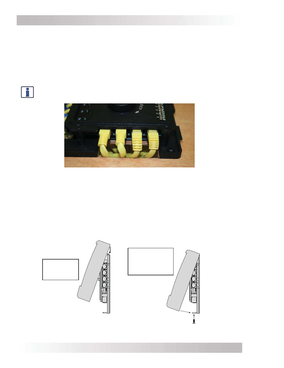
Figure 2-11, Connecting the Parallel Stack Cables to the Router
2.7.2
Connecting the Parallel Stack Cables
To connect the parallel stack cables:
1. Connect a stack cable to the Stack/Accessories port on every inverter installed in parallel (see
Figures 2-1 & 2-10).
2. Route the inverter-connected stack cables from each inverter/charger to your router. Depending
on your particular setup, the cables may need to be routed through walls or the MP panel
enclosure system.
3. Connect each stack cable to its respective stack port on the router (MA, SL1, SL2, and SL3
ports for the appropriate number of inverters installed in parallel). See Figure 2-11.
Info: At least one stack cable must be plugged into the router’s MA port in order for
the router to operate any inverters.
Push front cover
down fl ush, and
install screws in
bottom tabs.
Place front
cover over
tabs at top.