0 setup, 1 power-up routine, 2 navigating the router – Magnum Energy ME-RTR Router User Manual
Page 20
©
2014 Magnum Energy, Inc.
Page 12
Setup
Figure 3-1, System Home Screen
Off
29.3VDC 0ADC
ALL System Home
3.1 Power-up
Routine
When the router is first connected to an inverter, a power-up routine is initialized. During the
power-up routine, the LCD displays “MAGNUM ENERGY, Self Test, ME-RTR, and Version 3.1” for
approximately 5 seconds. The next three Set System Clock screens prompt you to set the current
time (HOURS, MINUTES, and AM/PM). Once the clock is set, the System Home screen is displayed.
3.0 Setup
When a router is connected to a Magnum inverter/charger, the settings in the router determine the
inverter/charger’s operating parameters. This section shows you how to navigate the router and
gives you an understanding of the function of each adjustable setting. See Figures 4-1 through 4-5
for complete maps of the router’s menu items and adjustable settings.
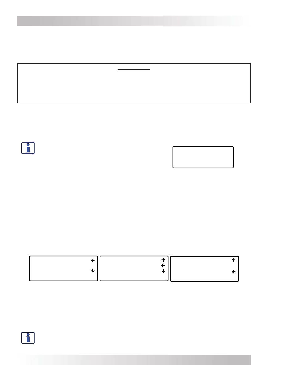
02 AC Meters
03 Timers
04 AGS Meters
ALL Select METER
01 DC Meters
02 AC Meters
03 Timers
ALL Select METER
03 Timers
04 AGS Meters
05 BMK Meters
ALL Select METER
Figure 3-2, Up and Down Arrows for Hidden Lines
3.2 Navigating the Router
Familiarize yourself with the controls on the front panel which are used to fi nd, adjust, and save
the desired settings (refer to Figure 1-1). They are:
• LCD Display – The 4-line LCD display shows status and operation information for the inverter/
charger and any attached accessories. All setup menus and faults also appear on the LCD display. If
there are more choices than will fi t on the screen, up and down arrows are present to guide you in
accessing those choices. An up arrow indicates you must rotate the SELECT knob counterclockwise
to display the next line. A down arrow requires a clockwise rotation. If both an up and down arrow
display, rotate the SELECT knob clockwise or counterclockwise to display all the hidden lines. See
Figure 3-2 below for an example of a screen sequence.
*** IMPORTANT ***
All settings/setup menus in the router are compatible with MS-PAE/MS-PE Series inverter/
chargers. If you are using the router with an inverter/charger other than the MS-PAE/MS-PE
Series, some features and setup menus may not be compatible and will not function. Refer to
Appendix B to determine if a particular feature/setup menu is compatible with your inverter.
Refer to Appendix C for additional information on using the router with non-stacked inverters.
• Menu Buttons (x5) – These buttons allow simple access to menu items for confi guring,
monitoring, and troubleshooting your inverter/charger system.
• Rotary SELECT Knob – This rotary knob allows you to quickly scroll through and select various
menu items and settings. Pressing the knob selects the menu item to change, or saves the current
selection.
Info: The “
←” (left facing arrow) symbol indicates that the displayed setting has been
selected and will be used (if the menu item is blinking, it has not yet been selected;
press the SELECT knob to select that menu item). Refer to Figure 3-2 for an example.
Info: Pressing and holding down the METER button
for three seconds takes you back to the System
Home screen (Figure 3-1) from any menu. The
LCD display automatically returns to the System
Home screen if no buttons have been pressed for
fi ve minutes.