9 wiring the auxiliary (aux) relay – Magnum Energy ME-RTR Router User Manual
Page 19
Page 11
©
2014 Magnum Energy, Inc.
Installation
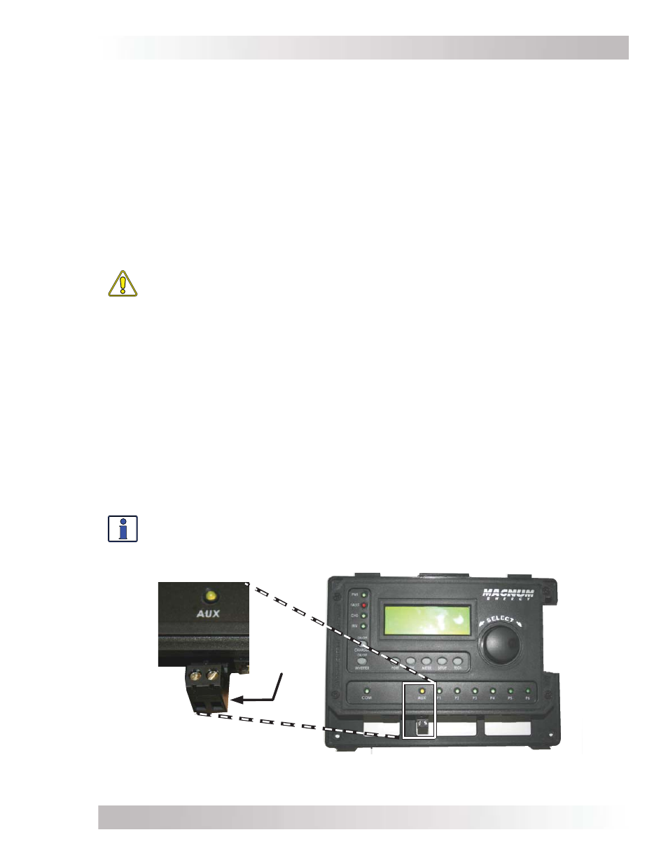
2-wire dry
contact
terminal
Figure 2-13, Wiring the Auxiliary Relay
2.9
Wiring the Auxiliary (Aux) Relay
The Aux Relay provides a 2-wire dry contact relay (i.e., no voltage provided) that is either open
or closed, and can be wired to any device requiring a contact closure to operate. For example, it
can be used as a signal relay to power a higher current relay.
Relay Information
• A single-pole, single-throw relay provided with the NO (Normally Open) and COM contacts.
• Contact rating: up to 30 VDC @ 1 amp, and from 31 VDC up to 60 VDC @ .25 amp.
• Opens if power to the router (provided through the inverter remote cable) is lost.
• Provides “dry contact” connections (it does not provide any voltage or current)—power for any
external device requiring voltage or current must be provided through the relay.
• This relay is not intended to directly provide power. Rather, this relay can be used to send a
signal to operate the coil of another higher amperage device that does the actual switching
of power.
CAUTION:
• Any voltage connected to the relay must be less than or equal to the relay’s contact
ratings (Contact Ratings: ≤ 1A up to 30 VDC, ≤ .25A from 31 VDC to 60 VDC).
• An in-line fuse rated up to 1 amp (up to 30 VDC) or .25 amp (from 31 VDC to
60 VDC) must be used to protect all power circuits connected to the Aux Relay
(do not fuse ground connections). The fuse should be located as close as possible
to the power source. A fuse must be used, even if the circuit is providing only a
“dry contact” or “ground” connection—it will prevent damage if the connection is
miswired or damaged. Ensure the fuse is correctly rated for the wire size used. Refer
to national and local codes for rating and type.
• The Aux Relay circuit is not rated for AC volts and may cause damage if used.
• The warranty does not cover damage to this relay.
Relay Terminal Block
The Aux Relay is wired through an Euro-style removable connector (Figure 2-13). The connector
provides a two-port screw-type terminal block for wiring. This terminal block is friction-fi t into the
connector and can be removed by pulling it straight out. Each port on the terminal block accepts
a CU/AL single wire from #28 to #12 AWG (0.3 to 2.3 mm²).
Info: For information on setting the Aux Relay, refer to the CTRL: 04 RTR Aux Relay
menu.