Magnum Energy ME-RTR Router User Manual
Page 10
©
2014 Magnum Energy, Inc.
Page 2
Introduction
•
Menu Buttons (x5) – Allow the inverter or charger to be confi gured to your specifi c system
preferences. These buttons also allow simple access to menu items that can help with monitoring
and troubleshooting your inverter/charger system.
PORT Button – This button accesses the six communication and accessory ports to display
information on the connected devices.
CTRL Button – This button is used to select inverter, charger, and AGS functions previously
set up using the SETUP button.
METER Button – This button is used to access ‘read only’ DC, AC, Timer, AGS, and BMK
meters.
SETUP Button – This button is used to access the setup menus for the inverter, charger,
AGS, and BMK. The SETUP button may be password protected to keep unauthorized users
from accessing the SETUP menus.
TECH Button – This button is used to access technical information, fault history, and to set
a password for the SETUP button.
•
Auxiliary (Aux) Relay – The ME-RTR provides an Auxiliary Relay (Item G below)that can be
programmed to work either as a voltage-controlled relay (stays opened or closed based on VDC,
and activates either as an active high or active low type relay with an adjustable time delay),
a SOC-controlled relay (stays opened or closed based on the battery’s state of charge*), or
used as an inverter fault detection relay (opens if an inverter fault occurs). See Section 2.9 for
more information on this relay, as well as how to wire and set up the Aux Relay (using CTRL
button’s 04 RTR Aux Relay menu).
* Requires the optional ME-BMK (Battery Monitor Kit) to be installed.
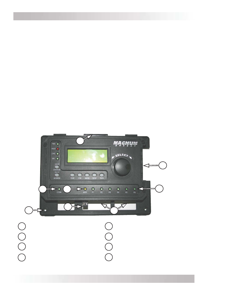
Figure 1-2, Router Features (front cover removed)
B
F
E
D
C
G
A
H
A
B
C
D
Mounting tabs for front
cover
Parallel Stack ports (x4)
Six LEDs for communication
(P1-P6)
LED for future use
(not functional)
E
F
G
H
LED for Aux Relay operation
Mounting screw holes (x4)
Aux Relay 2-wire terminal
w/ removable plug
Six Comm (Communication) ports
(P1-P6)