0 me-rtr menu maps – Magnum Energy ME-RTR Router User Manual
Page 55
Page 47
©
2014 Magnum Energy, Inc.
Menu Maps
4.0 ME-RTR Menu Maps
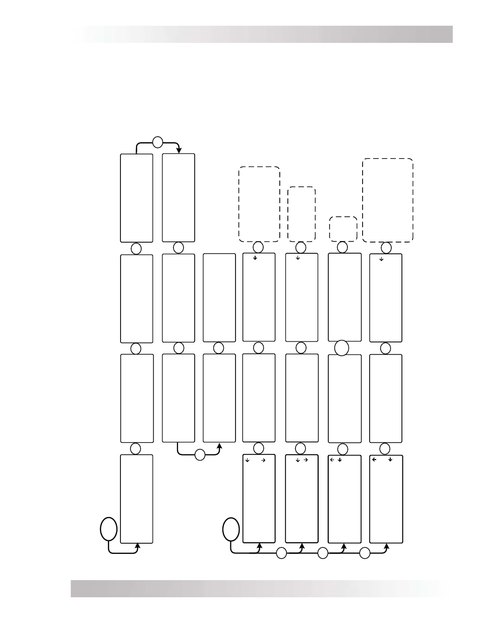
Figures 4-1 thru 4-5 are an overview of the settings and information displays available from the
router’s menu buttons (see Sections 7.2.5 and 8.2.3 for overviews of router menus for an attached
AGS and BMK, respectively). Figure 4-2 includes a port-specifi c METER menu for a connected
inverter.
Figure 4-6 provides a legend key for the symbols used in these menu displays. Refer also to
Appendix A in the back of this manual for a glossary of abbreviations that may appear on the
router’s LCD display. Note: When applicable, defaults and ranges are listed for a 24-volt battery.
Figure 4-1, PORT/CTRL Button Menu Maps
From the System Home Screen
PORT
1 INV
2 INV
3 Empty
4 BMK
5 RC
6 Empty
ALL Port Home
1 AGS
2 Empty
3 Empty
4 Empty
5 Empty
6 Empty
ALL Acc Home
MS4024PAE Master
Inverting
29.3VDC 0ADC
P1 INV Home
Auto Gen Start
Gen Off 0.0Hrs
14.4VDC TS Open
P1A AGS Home
MS4024PAE Slave
Inverter Standby
29.3VDC 0ADC
P2 INV Home
Empty Port
P3 Home
Remote Control
MS4024PAE on Port 1
P5 RC Home
Battery Monitor
FacFault -103AHrs
27.22VDC -101.4ADC
P4 BMK Home
Empty Port
P6 Home
R
R
R
R
R
R
R
R
Note:
PORT displays
shown are examples. Your displays will depend on the particular devices connected, and the ports to which you choose to connect them.
CTRL
01 AC In Control
02 Charger Control
03 Gen Control
ALL Select CTRL
01 AC In Control
Auto Connect
ALL View ACI CTRL
Set AC In Control
Auto Connect
ALL edit ACI CTRL
01 AC In Control
02 Charger Control
03 Gen Control
ALL Select CTRL
Set Charger Control
Multi-Stage
ALL edit CHG CTRL
02 Charger Control
03 Gen Control
04 RTR Aux Relay
ALL Select CTRL
P
P
02 Charger Control
Multi-Stage
ALL View CHG CTRL
03 Gen Control
No AGS Present
ALL Read AGS CTRL
P
03 Gen Control
OFF
ALL Read AGS CTRL
OR
Options available only if an AGS is connected.
P
P
Multi-Stage
Start Float
Start Bulk
Auto Connect
VDC Connect
Time Connect
SOC Connect
AC In - Disabled
OFF
ON
AUTO
R
R
R
R
02 Charger Control
03 Gen Control
04 RTR Aux Relay
ALL Select CTRL
R
R
04 RTR Aux Relay
Force Open
ALL View SYS CTRL
Force Open
Force Closed
Auto VDC
Auto VDC (BTS Comp)
Auto Fault
Auto SOC
P
P
Set RTR Aux Relay
Force Open
ALL edit SYS CTRL
R