Pls> input and output register map, Pls> working register – Yaskawa MP2000 User Manual
Page 168
TECHNICAL NOTE
File: MP2000_IndividualFunctionDocument_RevC 168/168
Doc Number: eng.MCD.05.101
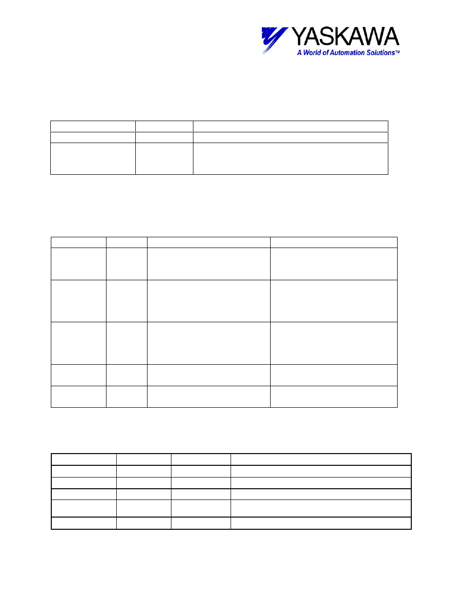
Output Registers
The following registers are used as outputs from the function block. They can be
monitored by the LadderWorks program to check the execution of the function.
Output Type
Description
RUNNING
Bit
Goes true if block is enabled.
OUTPUT
Bit
Goes true when Counter input value is within
the LOWLIMIT and HILIMIT inputs and the
EXECUTE
input is True.
Input Registers
The following registers are used as inputs to the function block. They select the
options and define the parameters that the user needs to make the Home function work
as necessary.
Input
Type
Description
Range and state
EXECUTE Bit
Block enable – Block cannot
execute unless this is
TRUE.
True-effective
False-invalidity
LOWLIMIT Long
Defines the output enable
window. Minimum value of
counter for OUTPUT output
to go TRUE
-2147483648~2147483647
HILIMIT
Long
Defines the output enable
window. Maximum value of
counter for OUTPUT output
to go TRUE
-2147483648~2147483647
COUNTER Long
The controlling counter for
the bit
A long register containing the
counter value.
DATA02W Addres
s
Address of the first working
register.
Two words of register space
are used by this function.
This table outlines the data in the two registers used by the function block. There is not
usually any need for the user to access any of these bits directly.
Register No
TYPE
Name
Description
AW00000
Bit
0
IN
execute
EXECUTE
input (XB000000)
Bit A
IN
oneshotA
Reserved
Bit B
IN
firstPass
One shot coil from rising edge of EXECUTE input to initiate
block.
AW00002
Working
Revision
Revision Level of the function block.