Asciiin> input and output register map – Yaskawa MP2000 User Manual
Page 155
TECHNICAL NOTE
• This function expects the characters to be received from the source in a
continuous stream (Note: if testing is performed by typing in one character at a
time from a keyboard, the data reception MSG-RCV will time-out, and only the
first character will be received, and the DONE signal will come on).
• Thirty words are used as working registers for this function, starting at the
address in Data30W
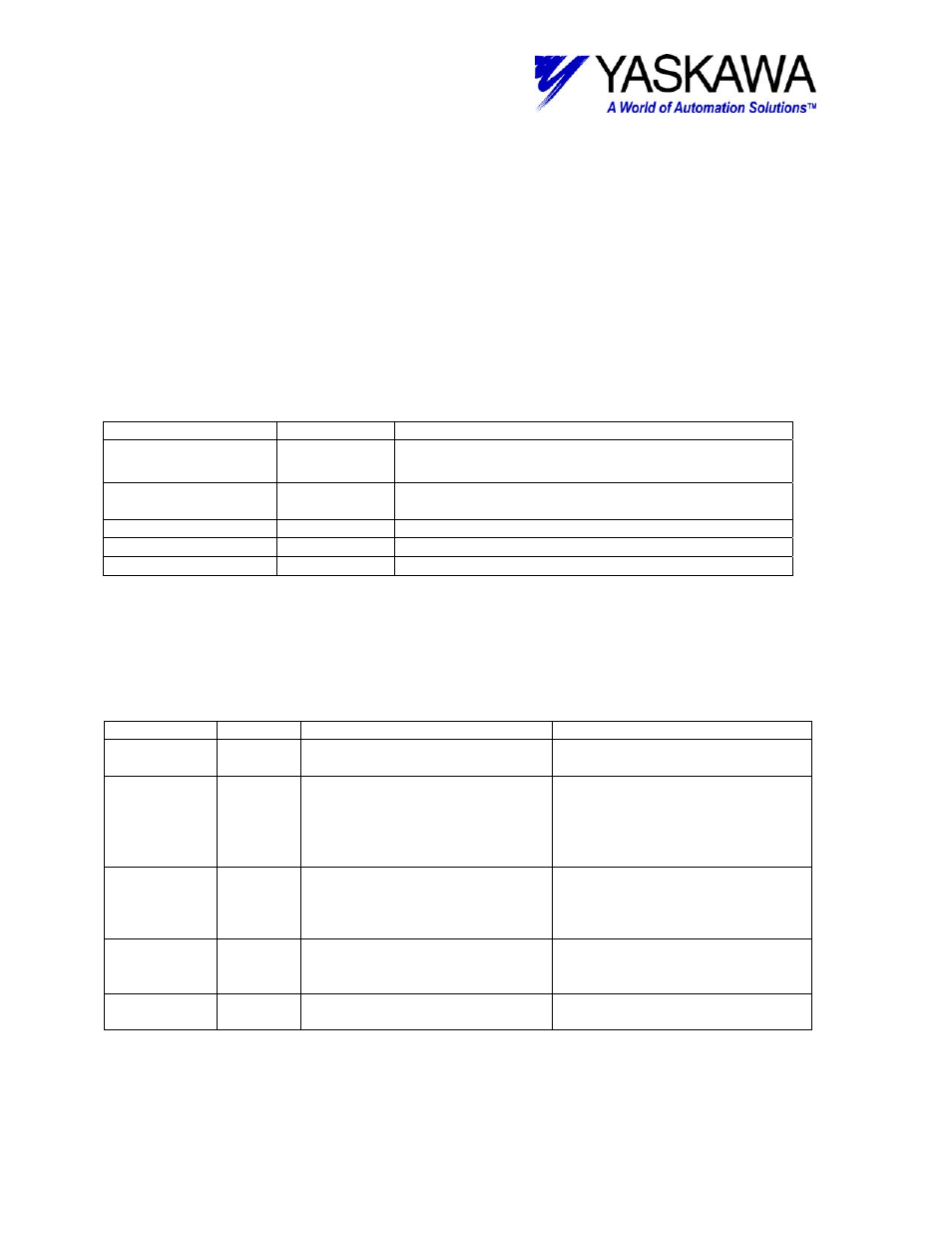
Output Registers
The following registers are used as outputs from the function block. They can be
monitored by the LadderWorks program to check the execution of the function.
OUTPUT TYPE
Content
BUSY
Bit
High while block is receiving data and there are no
errors.
DONE
Bit
Goes high when receiving is completed and remains
high until execute is turned off.
ERROR
Bit
Goes high if any error occurs in block or on the axis
ERROR-ID
Word
Displays the value of the error in block.
NUMCHRIN
Word
Displays the number of characters received.
Input Registers
The following registers are used as inputs to the function block. They select the options
and
define the parameters that the user needs to make the function work as necessary.
INPUT
TYPE
Content
Range of State
EXECUTE
Block enable – Block cannot
execute unless this is TRUE.
TRUE – Block enable
FALSE – Block disable
START
Word
Starting address to store ASCII
set. This is fed directly into
Param12 of MSG-RCV function.
This is the address for an M-
register type
0-29999(unused M register area)
and 30000 and higher have been
reserved by the RDA parameter.
SIZE
Word
Maximum number of ASCII
characters to be received. Start +
Size is fed directly into Param13
of MSG-RCV function
0~28767
CIR
Word
Which port is to transmitted from
For 217IF-01
1=Port 1 (RS-232C)
2=Port 2 (RS-422/485)
DATA30W
Address Address of the first working
register.
Thirty words of register space are
used by this function.
File: MP2000_IndividualFunctionDocument_RevC 155/168
Doc Number: eng.MCD.05.101
11/17/2005