Tuning>input and output register map – Yaskawa MP2000 User Manual
Page 114
TECHNICAL NOTE
• Six words are used as working registers for this function, starting at the address
in Data06W.
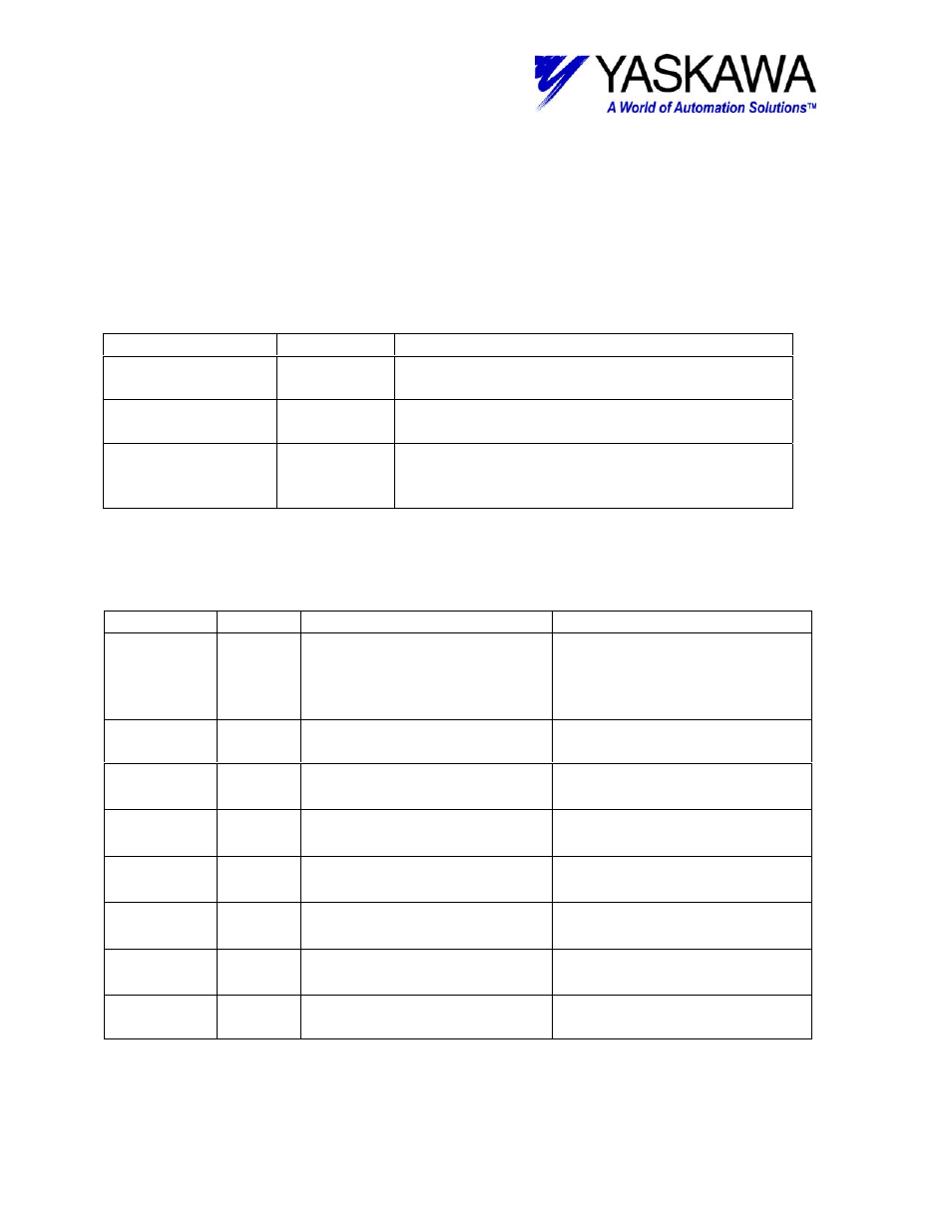
Output Registers
The following registers are used as outputs from the function block. They can be
monitored by the LadderWorks program to check the execution of the function.
Output Type
Description
RUNNING
Bit
This bit is ON when the function block is
executing.
DONE
Bit
This bit is ON when the function block is
complete and there are no errors
ERROR
Bit
This bit is ON when one of the values is out of
range. However, if the error condition is
cleared, this output is reset to OFF.
Input Registers
The following registers are used as inputs to the function block. They select the options
and define the parameters that the user needs to make the function work as necessary.
INPUT
TYPE
Content
Range of setting and state
EXECUTE Bit
Block enable – Block cannot
execute unless this is
TRUE.
Rising edge initiates block
TRUE – Block enable
FALSE – Block disable, set
all outputs to zero and off
AXIS
Word
Axis number related to the
block
1~16
FEEDFWD Word
Speed Feed forward
0~100[%]
Set parameter OWxx30
SPDLOOP Word
Speed loop gain
1~2000[Hz]
Set parameter OWxx2F
POSLOOP Word
Position loop gain
10~20000[0.1/s]
Set parameter OWxx2E
SPD-TI
Word
Speed loop integral time
constant
15~32767[0.01ms]
Set parameter OWxx34
POS-TI
Word
Position loop integral time
constant
0~5000[ms]
Set parameter OWxx32
DATA06W
Address
Address of the first working
register.
Six words of register space
are used by this function.
File: MP2000_IndividualFunctionDocument_RevC 114/168
Doc Number: eng.MCD.05.101
11/17/2005