Asciiout> input and output register map – Yaskawa MP2000 User Manual
Page 161
TECHNICAL NOTE
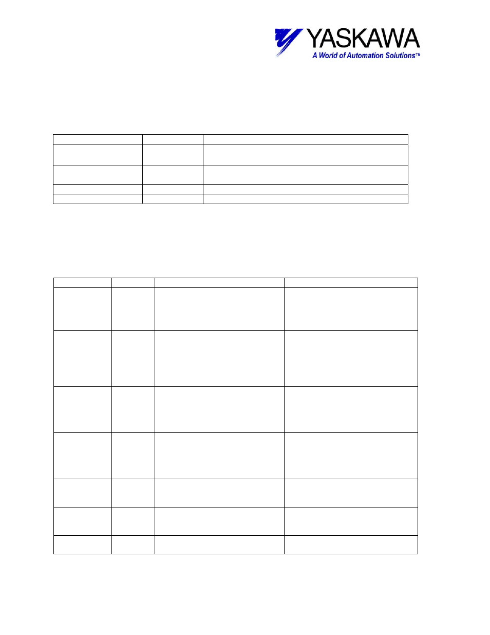
Output Registers
The following registers are used as outputs from the function block. They can be
monitored by the LadderWorks program to check the execution of the function.
Output Type
Description
BUSY
Bit
High while block is transmitting data and there are no
errors.
DONE
Bit
Goes high when transmission is completed and
remains high until execute is turned off.
ERROR
Bit
Goes high if any error occurs in block or on the axis
ERROR-ID
Word
Displays the value of the error in block.
Input Registers
The following registers are used as inputs to the function block. They select the options
and
define the parameters that the user needs to make the function work as necessary.
Input Type
Description
Range of State
EXECUTE
Bit
Block enable – Block cannot
execute unless this is TRUE.
Pos Edge – Block execute
TRUE – Block enable
FALSE – Block disable
CRLF
Bit
Inserts
a Carriage return and line
feed to the end of the table (takes
up one 16-bit word, table size
remains the same (note this will
overwrite the last word of the
table with the CrLf).
TRUE – CR and LF are added
FALSE – no addition
START
Word
Starting address of ASCII set.
This is directly written to Param5
of MSG-SND function. It will
represent the address of an M-
register type.
0-29999(unused M register area).
30000 and higher have been
reserved by the RDA parameter.
SIZE
Word
Number of ASCII characters to be
sent (number of bites), also
indicates table size
This is directly written to Param6
of MSG-SND function
0~28767
CIR
Word
Indicates the circuit number or
port number to send the
characters
For 217IF-01
1=Port 1 (RS-232C)
2=Port 2 (RS-422/485)
SLAVE
Word
Destination Station Number
This value is set in PARAM02 of
the MSG-SND function.
1~256
DATA23W
Address Address of the first working
register.
Twenty-three words of register
space are used by this function.
File: MP2000_IndividualFunctionDocument_RevC 161/168
Doc Number: eng.MCD.05.101
11/17/2005